Multilayer Capacitor

Inactive Publication Date: 2007-02-01
KYOCERA CORP
View PDF18 Cites 13 Cited by
  • Summary
  • Abstract
  • Description
  • Claims
  • Application Information

AI Technical Summary

Benefits of technology

[0027] In this case, the electrical characteristics achieved when a current flows in and out of the fifth terminal electrode and the sixth terminal electrode and the electrical characteristics achieved when a current flows in and out of the seventh terminal electrode and the eighth terminal electrode are different in series reson

Problems solved by technology

As described above, when a multilayer capacitor with a wide “effective frequency band” is employed for a decoupling circ

Method used


Image

  • Multilayer Capacitor
  • Multilayer Capacitor
  • Multilayer Capacitor

Examples


example

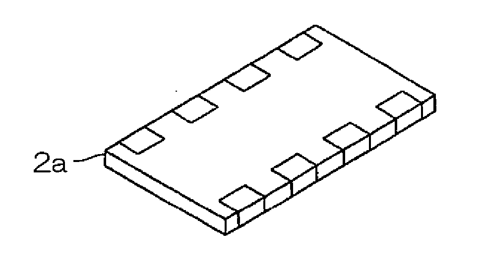
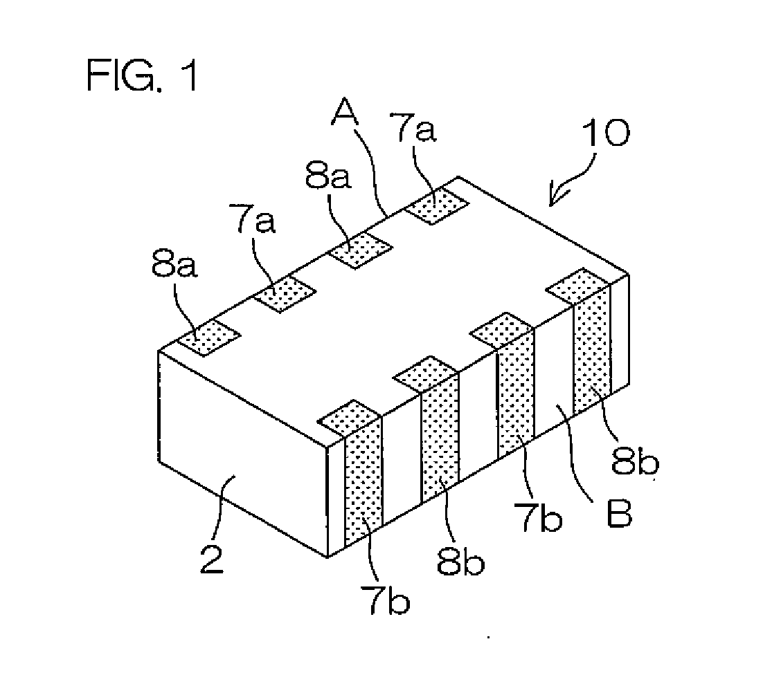
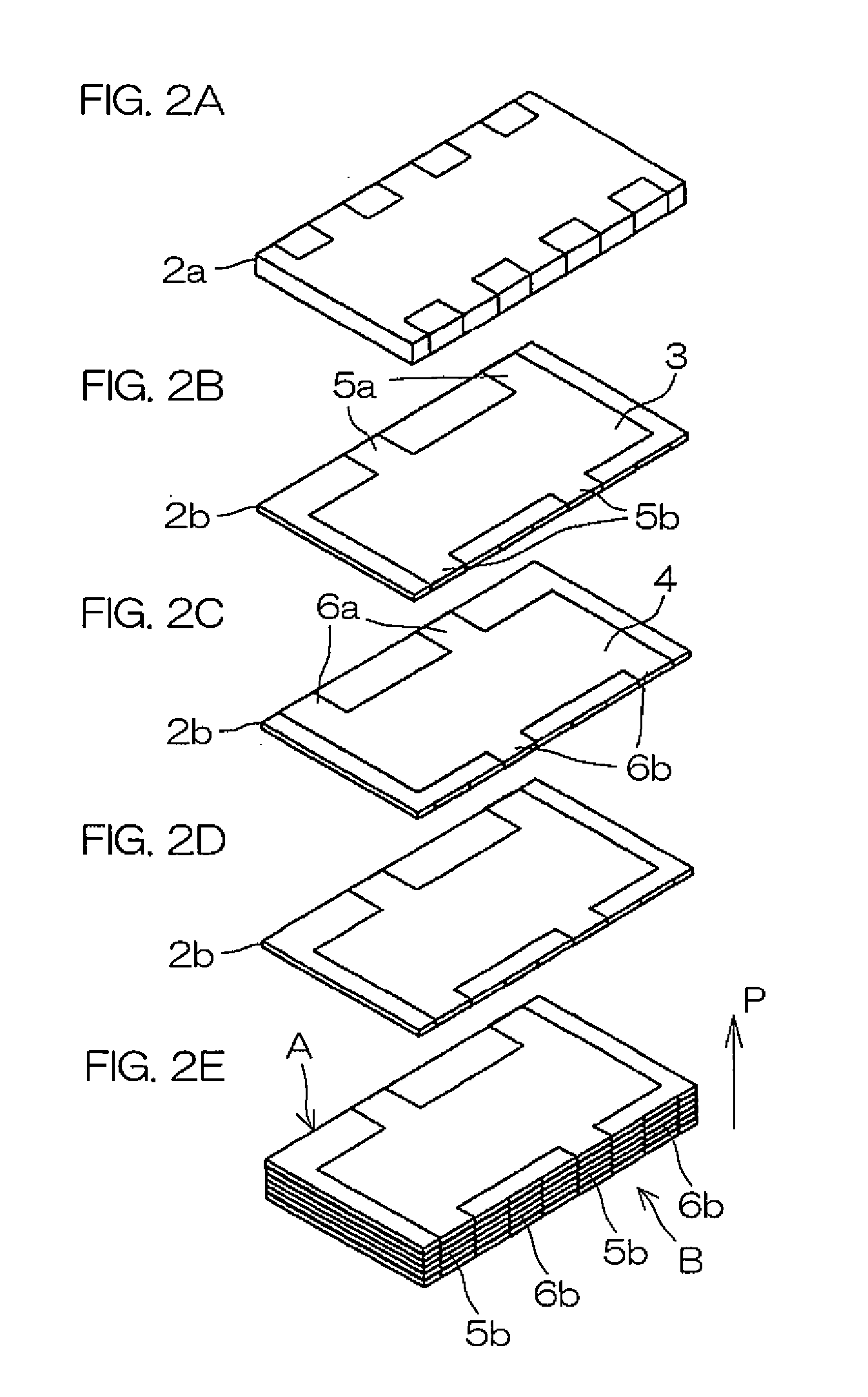
[0123] A plural number of dielectric layers comprising a dielectric material mainly composed of barium titanates were laminated together to produce a multilayer body 2 of 2.0 mm in length, 1.2 mm in width, and 0.85 mm in height. Fifty layers of first internal electrodes 3 and second internal electrodes 4 made of nickel were formed so that they were opposed to one another with dielectric layers interposed in between inside the multilayer body 2. A first terminal electrode 7 and second terminal electrode 8 were formed by baking copper on side surfaces of the multilayer body 2, which was then fired. A multilayer capacitor 10 was produced in the foregoing way.

[0124] The extension portions were formed, as shown in FIGS. 2A-2E and FIGS. 3A and 3B, by extending two portions to a couple of opposed lateral sides A and B, respectively, of the multilayer body. The width with respect to the extending direction was 100 μm, and the lengths in the extending direction and the shapes of the interna...


PUM

PropertyMeasurementUnit
Lengthaaaaaaaaaa
Areaaaaaaaaaaa
Frequencyaaaaaaaaaa

Abstract

A multilayer capacitor according to the present invention comprises a multilayer body 2 including a plurality of dielectric layers laminated together, first internal electrodes 3 and second internal electrodes 4 that are arranged alternately with the dielectric layers interposed therebetween inside the multilayer body 2, first extension portions 5a extended from the first internal electrodes 3 to one lateral side A of the multilayer body 2 at one or a plural number of locations, and second extension portions 5b extended from the first internal electrodes 3 to another lateral side B of the multilayer body 2 at one or a plural number of locations, wherein the length of the first extension portions 5a is different from the length of the second extension portions 5b. As a result, the multilayer capacitor according to the present invention have electrical characteristics combining two electrical characteristics in which series resonance points are formed at different frequencies, the “effective frequency band” with low impedance is widened.

Description

BACKGROUND OF THE INVENTION [0001] 1. Field of the Invention [0002] The present invention relates to a multilayer capacitor which is suitably used for decoupling circuits and the like for supplying electric power from a power source to circuitry such as IC (Integrated Circuit). [0003] 2. Description of Related Art [0004] A decoupling circuit is a circuit which is connected between an IC and a power source for suppressing fluctuations in voltage by rapidly charging or discharging in response to fluctuations in electric current supplied from the power source to the IC. [0005] The function to rapidly charge or discharge electric current is attained by decreasing impedance of the decoupling circuit. [0006] A desirable decoupling circuit has electrical characteristics with a wide frequency band in which impedance is low (referred to as “effective frequency band”). Owing to this, current fluctuations including those occurring at low frequencies as well as those occurring at high frequenci...

Claims


Application Information

Patent Timeline
IPC IPC(8): H01G4/005
CPCH01G4/012Y10T29/435H01G4/30
Inventor TAKAHASHI, AKIHIRO
Owner KYOCERA CORP
Why Eureka
Try Eureka