

Receiver apparatus and information recording/outputting apparatus
a technology of information recording/output and receiver, which is applied in the direction of selective content distribution, television systems, instruments, etc., can solve the problems of increased manufacturing cost, increased so-called splitting loss, and attenuation of signal level
- Summary
- Abstract
- Description
- Claims
- Application Information
AI Technical Summary
Benefits of technology
Problems solved by technology
Method used
Image

Examples
first embodiment
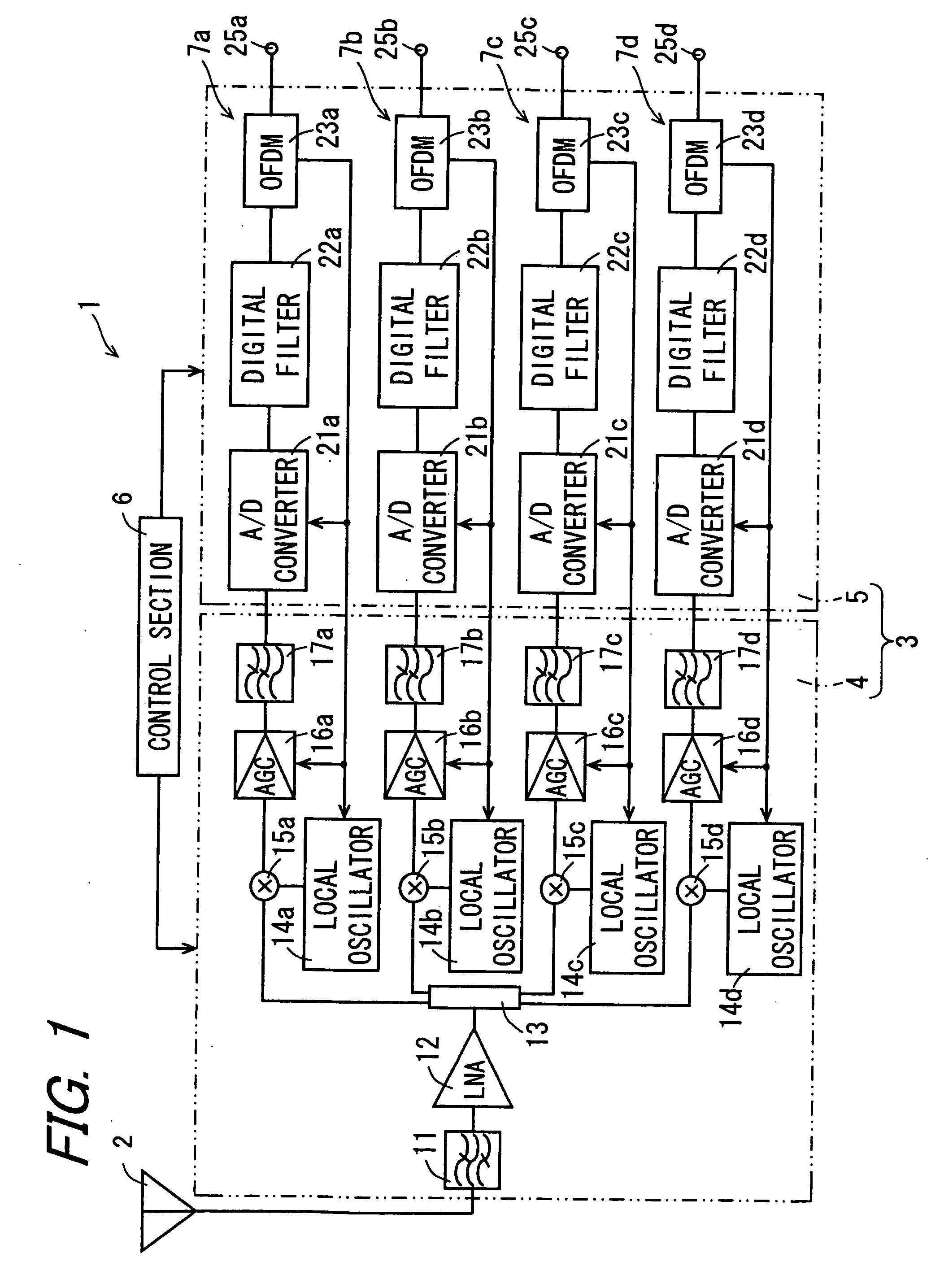
[0134]FIG. 1 is a block diagram showing the configuration of a receiver apparatus 1 according to the invention. The receiver apparatus 1 is configured to include a tuner module section 3, and a control section 6. The tuner module section 3 includes a first signal processing unit 4, and a second signal processing unit 5.
[0135] The first signal processing unit 4 is configured by a semiconductor integrated circuit (IC), and includes a band pass filter (BPF) section 11, a low noise amplifier (LNA) 12, a splitter 13, a first local oscillator 14a, a second local oscillator 14b, a third local oscillator 14c, a fourth local oscillator 14d, a first mixer unit 15a, a second mixer unit 15b, a third mixer unit 15c, a fourth mixer unit 15d, a first automatic gain control (AGC) section 16a, a second AGC section 16b, a third AGC section 16c, a fourth AGC section 16d, a first low pass filter (LPF) section 17a, a second LPF section 17b, a third LPF section 17c, and a fourth LPF section 17d.
[0136] T...
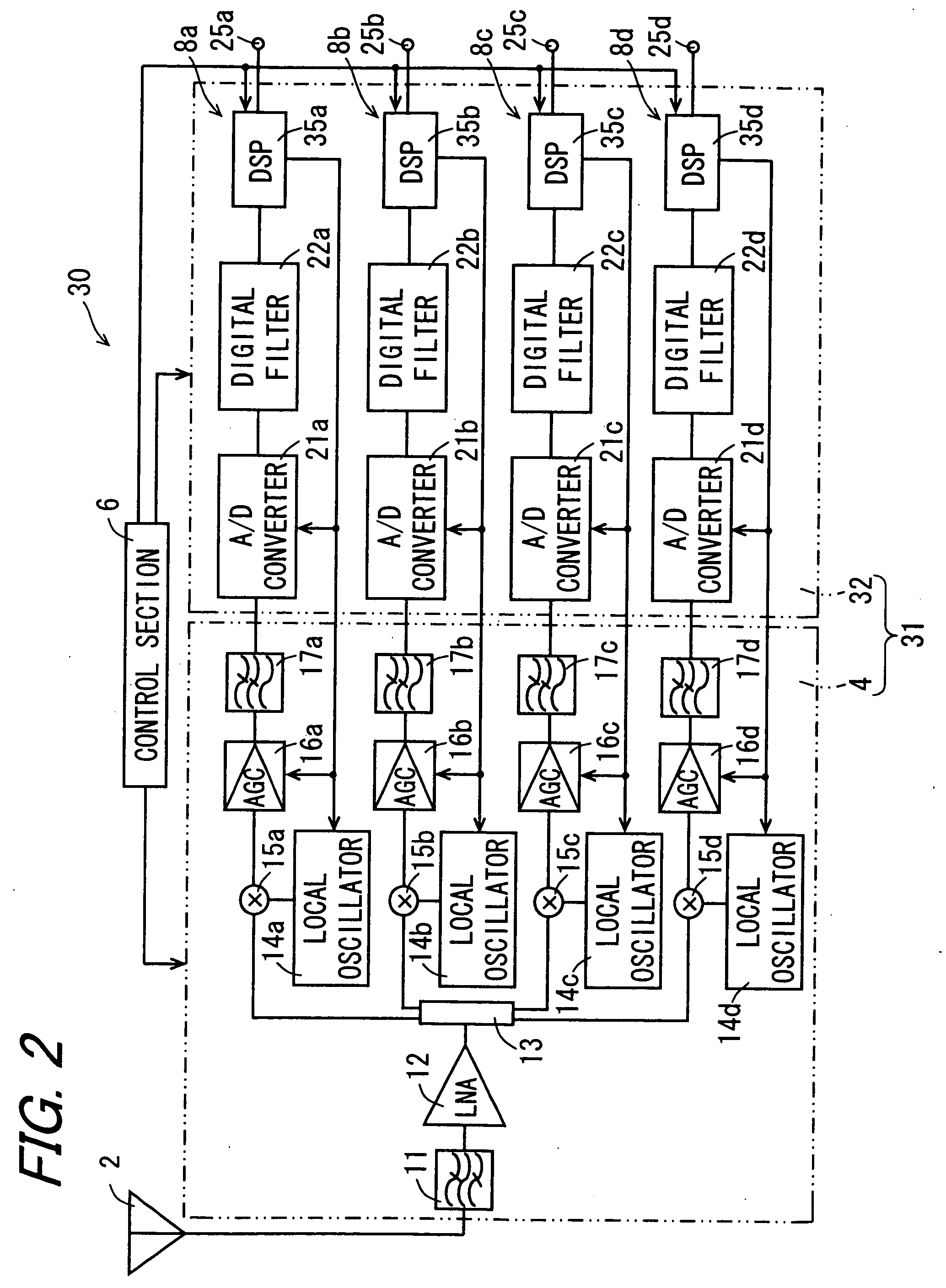
second embodiment
[0177] As described above, according to the invention, the demodulation unit is configured by the DSP 35. The DSP 35 can change the demodulation program from one to another with relative ease based on a predetermined command provided from the control section 6, i.e., a command of changing the predetermined demodulation program to another. The DSP 35 can also rewrite the demodulation program recorded on the DSP 35 with relative ease based on a command provided from the control section 6, more specifically, a command of rewriting the demodulation program previously recorded on the DSP 35 to another, and the demodulation program data.
[0178] As such, by changing the demodulation program previously recorded on the DSP 35 based on the transmission scheme, the receiver apparatus 30 can demodulate any signal input to the DSP 35 with relative ease by following the demodulation program suiting the transmission scheme. The receiver apparatus 30 is not required to include any specific demodulat...
third embodiment
[0199] As described above, according to the invention, the A / D converter is the ΔΣ A / D converter 48. By using such a ΔΣ A / D converter 48, the mixed signal provided from the AGC section 47 of the first signal processing unit 42 can be converted into a digital signal with high precision. In other words, it becomes possible to derive any highly precise digital signal with no influence of noise entering from the outside.
[0200] As such, for signal processing for eliminating any noise entering from the outside into such components of the BPF section 11, the LNA 12, and the digital filter section 49, there is no need to insure high precision so that the load of the signal processing can be decreased in the BPF section 11, the LNA 12, and the digital filter section 49. This accordingly decreases the power consumption as much as possible in the BPF section 11, the LNA 12, and the digital filter section 49.
[0201] According to the third embodiment of the invention, the mixer unit 45 directly ...
PUM
 Abstract
Description
Claims
Application Information