

Device and method for monitoring at least one energy reserve capacitor in a restraint system
a technology of energy reserve capacitor and restraint system, which is applied in the direction of measurement device, resistance/reactance/impedence, instruments, etc., can solve the problems of less effective energy reserve voltage and vehicle battery voltage, and achieve the effect of eliminating the effect of battery voltage on the measurement and reducing the power loss during measuremen
- Summary
- Abstract
- Description
- Claims
- Application Information
AI Technical Summary
Benefits of technology
Problems solved by technology
Method used
Image

Examples
Embodiment Construction
[0018] A description is provided below of how, as the internal resistance of the energy reserve capacitor increases, the restraint system reacts correctly by indicating a dangerously high internal resistance when it occurs, in order to obtain replacement of the electronics. The signal may, for example, be given to the driver visually on the instrument panel by a display, an audible indication may be given or it is also possible, in addition, for contact to be made via a transmitting / receiving station, for example a mobile telephone, in order to contact a garage or other service establishment. The latter would then be able to inform the driver that replacement is necessary.
[0019] In order for the device according to the present invention to be operated or implemented, the following conditions should be met:
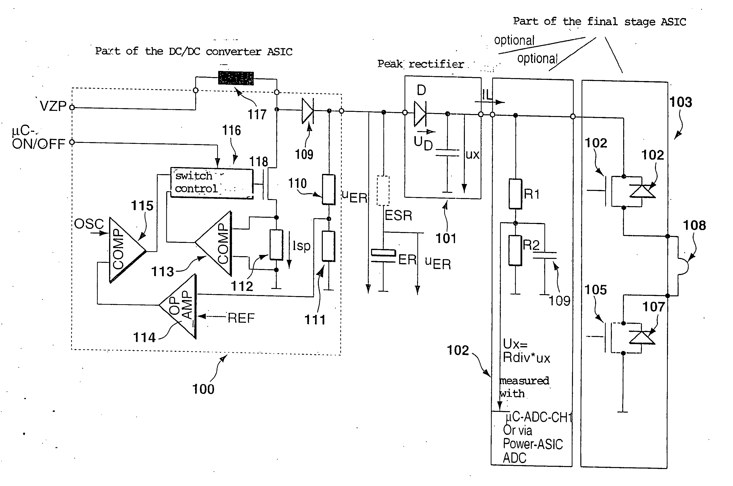
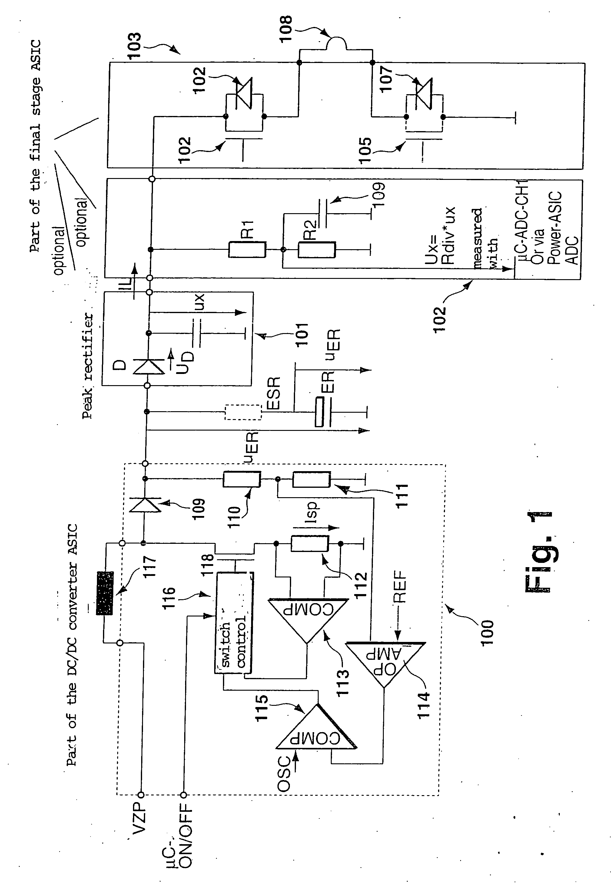
[0020] A clocked step-up converter of fixed or variable switching converter frequency is to be provided. The charging voltage of the energy reserve capacitor is ultimately above ...
PUM
 Abstract
Description
Claims
Application Information