Method of manufacturing a temperature compensated oscillator

a technology of temperature compensation and oscillator, which is applied in the direction of heat measurement, instruments, optical radiation measurement, etc., can solve the problems of large number of adjustment steps, inability to accurately adjust the temperature characteristics, and deviation between oscillation frequencies, etc., to achieve the effect of simplifying the adjustment steps and accurate adjustment of temperature characteristics

Inactive Publication Date: 2007-02-08
CITIZEN WATCH CO LTD
View PDF22 Cites 4 Cited by
  • Summary
  • Abstract
  • Description
  • Claims
  • Application Information

AI Technical Summary

Benefits of technology

[0024] The invention has been developed to solve the problems described above, and its aspect is to make it possible, in a state in which a piezoelectric element such as a quartz crystal or the like, an IC chip, and so on are mounted in a package to constitute a temperature compensated oscillator, to allow its oscillation circuit to operate so as to accurately adjust the temperature characteristics of the piezoelectric element itself, and thereafter subsequently create compensation data and store it into a compensation data storage circuit, thereby simplifying adjustment steps of the temperature compensated oscillator and increasing the accuracy thereof.

Problems solved by technology

However, the oscillation circuits cannot be sufficiently compensated if the quartz crystals 15 exhibit a wide range of characteristic variation, and it is therefore necessary to adjust as much as possible the characteristics of the quartz crystals 15 in advance.
Accordingly, there has been a problem that deviation arises between the oscillation frequency when the IC chip is also mounted in the package to make up the oscillation circuit together with the piezoelectric element and the circuit is caused to perform oscillation operation and the previously adjusted resonant frequency.
In addition, the number of adjustment steps has been large which requires extra adjustment cost.
This brings about a problem that it is impossible to perform appropriate adjustment of the resonant frequency of the piezoelectric element such as the quartz crystal or the like and proper creation of the compensation data thereafter.

Method used


Image

  • Method of manufacturing a temperature compensated oscillator
  • Method of manufacturing a temperature compensated oscillator
  • Method of manufacturing a temperature compensated oscillator

Examples


first embodiment

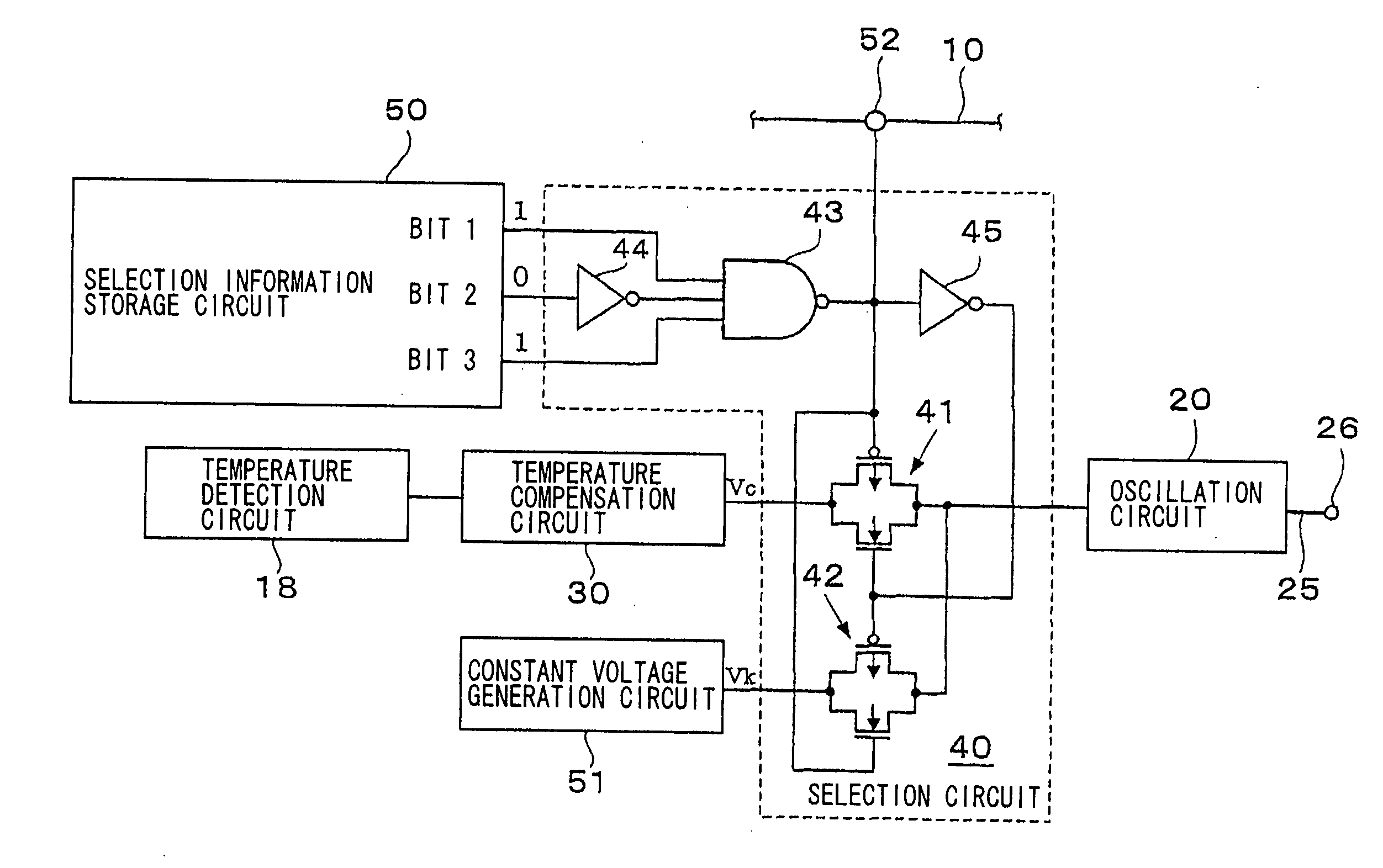
[0047]FIG. 1 is a block circuit diagram showing the configuration of a first embodiment of a temperature compensated oscillator according to the invention, in which portions equivalent to those in FIG. 8 and FIG. 9 are assigned the same numerals and symbols, and the description thereof will be omitted.

[0048] The temperature compensated oscillator shown in FIG. 1 comprises an oscillation circuit 20 having an output line 25 and an output terminal 26, a temperature detection circuit 18, and a temperature compensation circuit 30 which are similar to those of the conventional example shown in FIG. 9. The oscillator further comprises, as components specific to this embodiment, a selection circuit 40 that is a selection means, a selection information storage circuit (non-volatile memory) 50 which stores control information for controlling the selection state of the selection circuit 40, and a constant voltage generation circuit 51 which outputs a constant voltage Vk.

[0049] In addition to...

example 1

ANOTHER EXAMPLE 1 OF OSCILLATION CIRCUIT

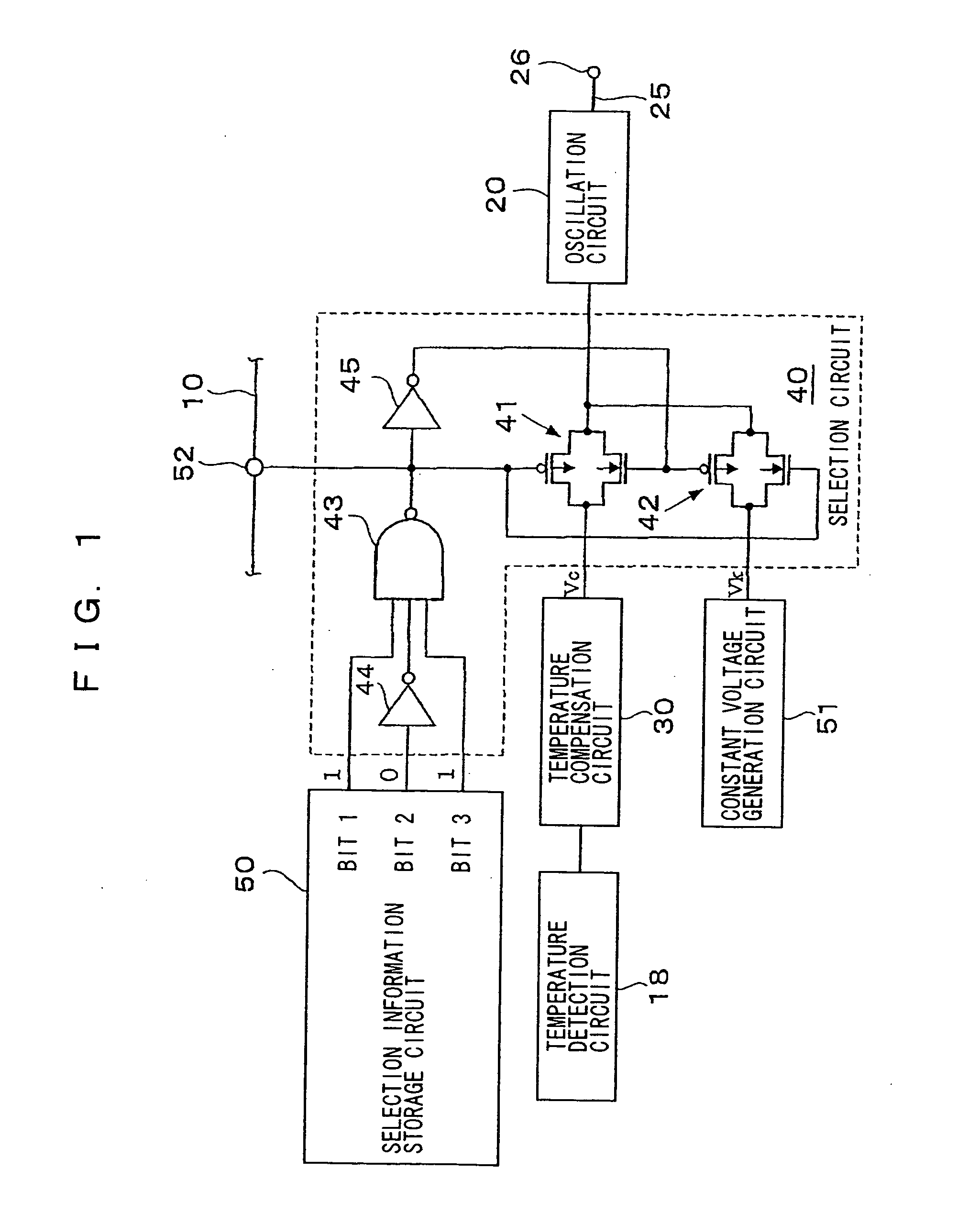
[0075] Next, another example of the oscillation circuit, in particular, its oscillation capacitor and it's capacitance variable means are shown in FIG. 2 and FIG. 3.

[0076] The oscillation circuit shown in FIG. 2 forms, similarly to the oscillation circuit 20 shown in FIG. 9, an inverter oscillation circuit in which a quartz crystal 15, an inverter 21, and a feedback resistor 22 are connected in parallel, and their both connection points are grounded via oscillation capacitors, respectively. As the each oscillation capacitor, however, parallel circuits composed of a plurality of fixed capacitors are used in place of the voltage controlled variable capacitor.

[0077] More specifically, a first capacitor array 27 in which capacitors C1 to C5 are connected in parallel via switches S1 to S5 is provided between the input side of the inverter 21 and the earth, and capacitors C6 to C10 are connected in parallel via switches S7 to S10 to form a second ...

example 2

ANOTHER EXAMPLE 2 OF OSCILLATION CIRCUIT

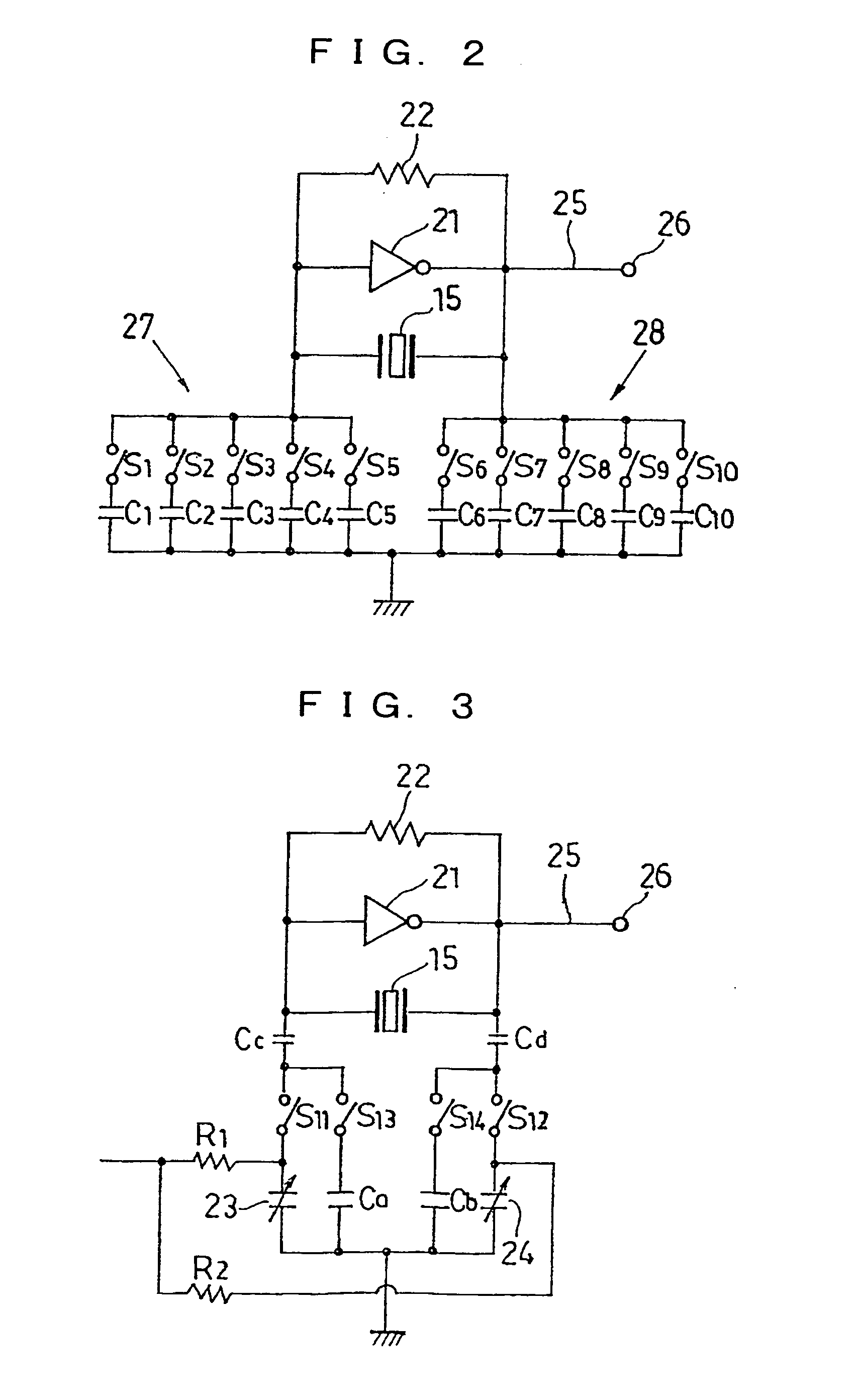
[0084] In the oscillation circuit shown in FIG. 3, series switches S11 and S12 are inserted into the voltage controlled variable capacitors 23 and 24 in the oscillation circuit 20 shown in FIG. 9, respectively, and a series circuit composed of a capacitor Ca and a switch S13 and a series circuit composed of a capacitor Cb and a switch S14 are connected in parallel to the series circuit including the switch S11 and the series circuit including the switch S12 respectively. The capacitors Ca and Cb are fixed capacitors and the capacitors Cc and Cd are DC component cut capacitors.

[0085] When the temperature compensation function is disabled at the time of initial adjustment, the switches S11 and S12 are turned off and the switches S13 and S14 are turned on by the selection circuit, whereby the oscillation capacitance is fixed to the capacitance values of the capacitors Ca and Cb. The voltage controlled variable capacitors 23 and 24 are brought in...


PUM


Abstract

A method of manufacturing a temperature compensated oscillator including the steps of assembling an oscillator in which an IC chip constituting a temperature compensation circuit with an oscillation circuit and a compensation data storage circuit, and a resonator for the oscillation circuit are mounted in a package; adjusting the resonator with an oscillation frequency of the oscillation circuit to a desired oscillation frequency in condition that the oscillator is kept at a reference temperature, in condition that a temperature compensation function of the temperature compensation circuit is disabled; sealing the resonator hermetically; creating temperature compensation data and storing it into the compensation data storage circuit; and enabling the temperature compensation function of the temperature compensation circuit.

Description

[0001] This application is a divisional of prior application Ser. No. 10 / 501,774, filed on Jul. 20, 2004 which is a §371 of International Application PCT / JP03 / 00422 filed on Jan. 20, 2003, the entire contents of which are incorporated herein by reference.TECHNICAL FIELD [0002] The present invention relates to a temperature compensated oscillator in which the frequency of an output signal is kept substantially constant irrespective of a change in ambient temperature and, more specifically, to a temperature compensated oscillator in which its temperature compensation function can also be disabled. BACKGROUND TECHNOLOGY [0003] Temperature compensated oscillators (TCXOs) used in various fields are in heavy use in portable mobile communication devices such as a cellular phone and so on in recent years. Generally, as this kind of temperature compensated oscillator, a crystal oscillator is widely used in which an oscillation circuit is constituted of a 10 MHz band AT cut quartz crystal (re...

Claims


Application Information

Patent Timeline
Patent Type & Authority Applications(United States)
IPC IPC(8): H03L1/00H03B5/32H03B5/04H03L1/02H03L7/18H03L7/183
CPCH03L1/026H03L7/183H03L7/18H03L1/027H03B5/04H03B5/32
Inventor SAKURAI, YASUHIRO
Owner CITIZEN WATCH CO LTD
Why Eureka
Try Eureka