
System and process for providing multiple beam sequential lateral solidification

a technology of sequential lateral solidification and multiple beams, which is applied in the direction of laser beam welding apparatus, solid-state devices, manufacturing tools, etc., can solve the problems of physical damage to the mask and damage to and achieve the effect of increasing the lifetime of the optics of the system and reducing energy

Inactive Publication Date: 2007-02-08
THE TRUSTEES OF COLUMBIA UNIV IN THE CITY OF NEW YORK
View PDF98 Cites 71 Cited by
  • Summary
  • Abstract
  • Description
  • Claims
  • Application Information

AI Technical Summary

Benefits of technology

[0006] One of the objects of the present invention is to provide an improved projection irradiation system and process to implement sequential lateral solidification. It is another object of the present invention is to provide a system and process to modify the microstructure of the thin film sample. It is another object of the present invention to provide a system and process where the mask utilized for shaping the laser beams and pulses is not damaged or degraded due to the intensity of the beams / pulses. It is also another object of the present invention to increase the lifetime of the optics of the system by decreasing the energy being emitted through the optical components (e.g., projection lenses).
[0010] In a further exemplary embodiment, the separated beams impinge on the thin film with a time delay, increasing the effective pulse duration and the irradiation of the beams on the sample.
[0011] In a further exemplary embodiment, the separated beams are forwarded through different optical paths to impinge and irradiate the thin film with a time delay, increasing the effective pulse duration and the irradiation of the beams on the sample.

Problems solved by technology

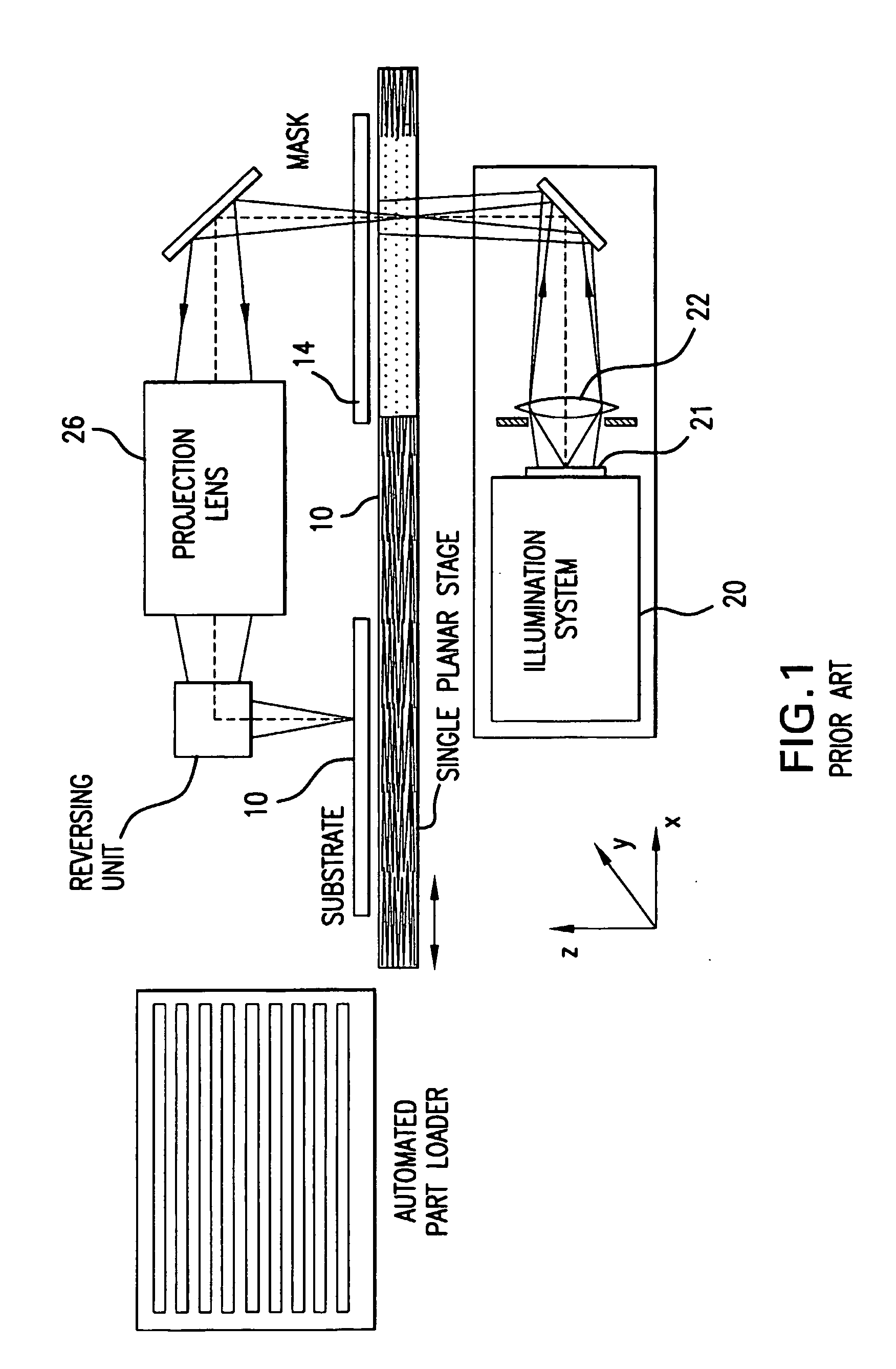
When the desired processes require high fluence on the substrate 10, the high energy density incident on the mask 14 can cause physical damage to the mask 14.
In addition, such high energy laser light can cause damage to the optics of the system.

Method used


Image

  • System and process for providing multiple beam sequential lateral solidification
  • System and process for providing multiple beam sequential lateral solidification
  • System and process for providing multiple beam sequential lateral solidification

Examples


Embodiment Construction

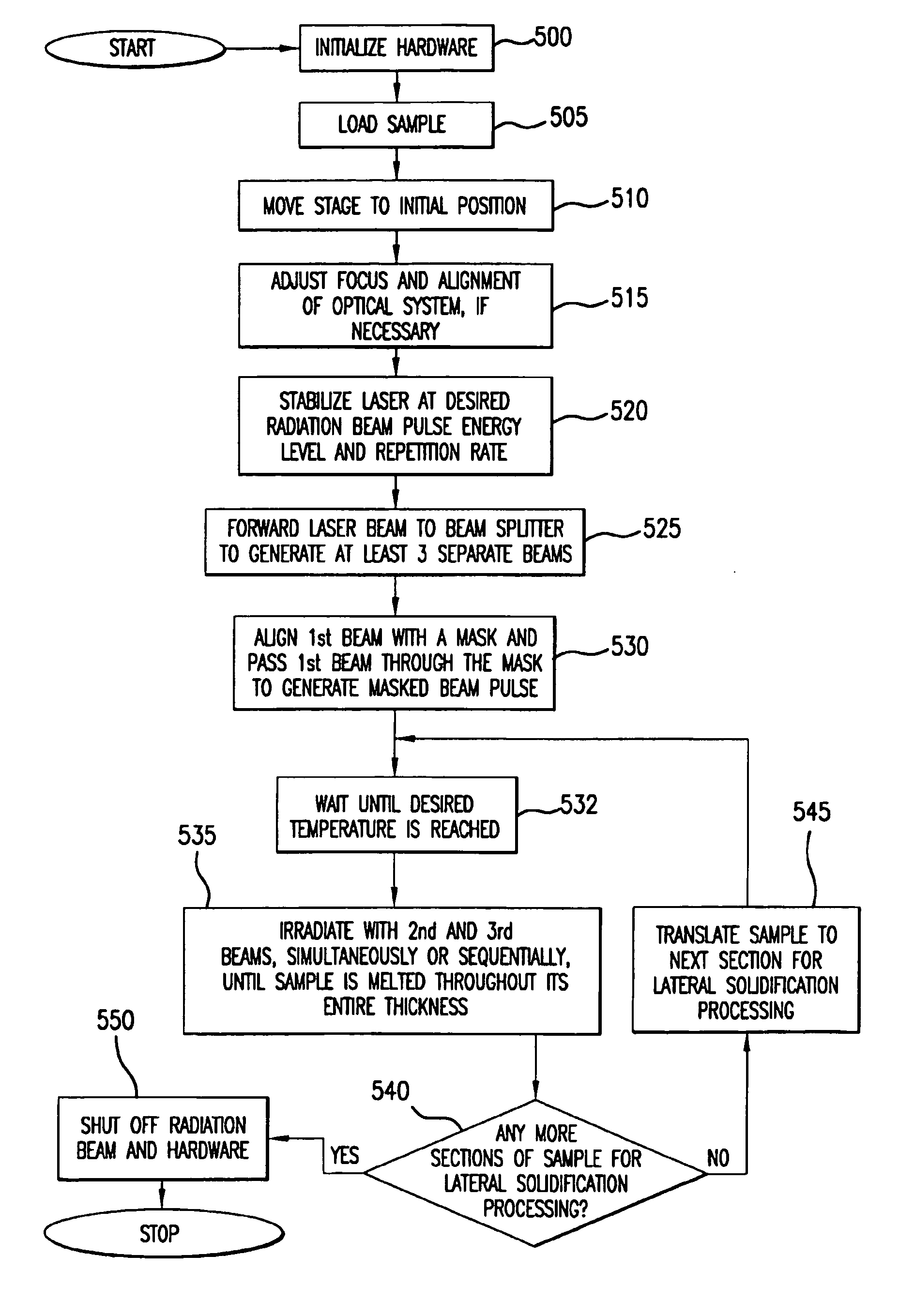
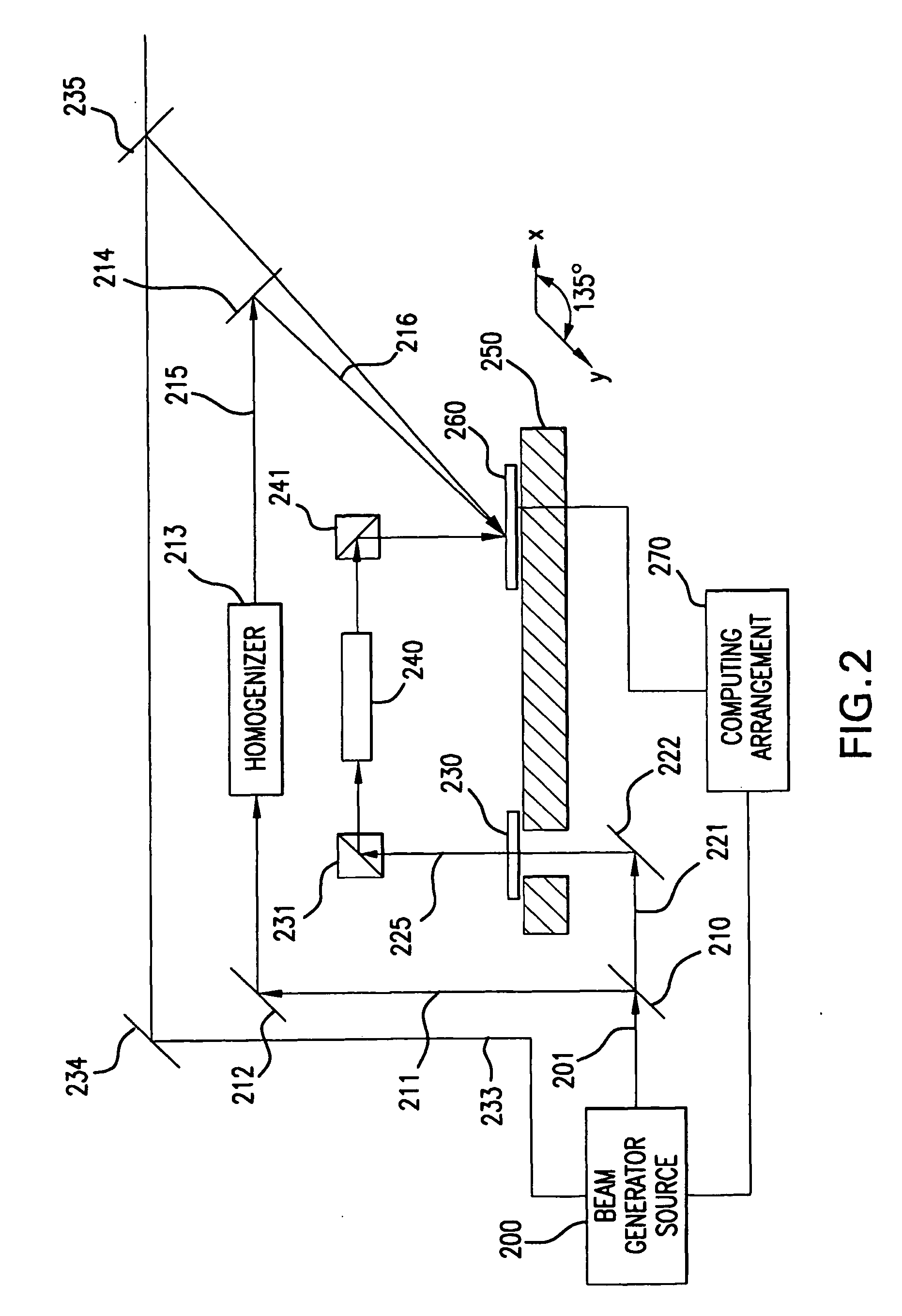
[0024] An exemplary embodiment of a projection irradiation system according to the present invention is shown as a schematic block diagram in FIG. 2. In particular, a beam source 200 (e.g., a pulsed excimer laser) generates an excimer laser beam 201 which passes through a beam splitter 210 to become a plurality of beams. In one exemplary implementation of the present invention, these the beam is split into three separate beams 211, 221, 233, where each has a lower energy than that of the original beam 201. Each of the beams 211, 221, 233 is composed of a set of beam pulses. It is within the scope of the present invention to possibly utilize other energy combinations with the exemplary system of the present invention illustrated in FIG. 2. It is also within the scope of the invention to use three beam sources or in the alternative to use a combination of beam sources and splitters to achieve the desired number of beams each at a particular energy level.

[0025] The first split beam 23...


PUM

PropertyMeasurementUnit
Timeaaaaaaaaaa
Thicknessaaaaaaaaaa
Transparencyaaaaaaaaaa

Abstract

A process and system for processing a thin film on a sample are provided. In particular, a plurality of separated beams each including beam pulses are generated. At least one first beam of the separated beams is forwarded through a mask to irradiate and heat the thin film sample prior to further irradiation. At least one second beam of the separated beams is then forwarded through a mask to further irradiate the thin film sample. Additional separated beams are sent through a mask to produce and further irradiate the thin film until the combined intensity of the beams impinging on the sample is sufficient to melt a section of the thin film throughout its entire thickness.

Description

FIELD OF THE INVENTION [0001] The present invention relates to techniques for processing of semiconductor films, and more particularly to techniques for processing semiconductor films using multiple patterned laser beamlets. BACKGROUND OF THE INVENTION [0002] Techniques for fabricating large grained single crystal or polycrystalline silicon thin films using sequential lateral solidification (SLS) are known in the art. For example, in U.S. Pat. No. 5,285,236 (“the '236 patent”) and U.S. patent application Ser. No. 09 / 390,537, the entire disclosures of which are incorporated herein by reference and which has been assigned to the common assignee of the present application, particularly advantageous apparatus and methods for growing large grained polycrystalline or single crystal silicon structures using energy-controllable laser pulses and small-scale translation of a silicon sample to implement SLS have been disclosed. The SLS techniques and systems described therein provide that low ...

Claims


Application Information

Patent Timeline
IPC IPC(8): H01L21/00H01L21/20H01LH01L21/77
CPCB23K26/0604B23K26/0608B23K26/0613B23K26/0656H01L27/1285H01L21/02532H01L21/02686H01L21/02691B23K26/067B23K26/066
Inventor IM, JAMES
Owner THE TRUSTEES OF COLUMBIA UNIV IN THE CITY OF NEW YORK
Learn More