Chemical vapor deposition of hydrogel films

a hydrogel film and chemical vapor technology, applied in chemical vapor deposition coatings, liquid surface applicators, coatings, etc., can solve the problems of limited bond-scission chemistry inside the chemical vapor deposition reactor, poor thickness control, and inability to demonstrate systematic control of crosslink density

Active Publication Date: 2007-02-08
MASSACHUSETTS INST OF TECH
View PDF22 Cites 44 Cited by
  • Summary
  • Abstract
  • Description
  • Claims
  • Application Information

AI Technical Summary

Benefits of technology

[0009] One aspect of the present invention relates to the use of initiated CVD (iCVD) to produce thin films of hydrogels (e.g., linear PHEMA homopolymers and crosslinked PHEMA copolymers) on a variety of surfaces. In one embodiment of the invention, iCVD is used to form linear thin films using a radical initiator and an alkene. In another embodiment, iCVD is used to form crosslinked thin films by the addition of a crosslinking agent (e.g., a diacrylate or a dimethyacrylate). The incorporation of a crosslinking agent into the thin films is shown to increase systematically with its partial pressure. In one embodiment, when the crosslinker is EDGA and the monomer is HEMA it results in crosslinked P(HEMA-co-EGDA) copolymer. In another embodiment, when the crosslinker is EDGA and the monomer is VP it results in crosslinked P(VP-co-EGDA). Disclosed are the effects of crosslinker incorporation on the thermal and wetting properties of the polymers. The unique swelling properties of these films are also disclosed, establishing that certain inventive films function as hydrogels when soaked in water.

Problems solved by technology

CVD can also be used to coat nanoscale features, as there are no surface tension and non-uniform wetting effects that are typically associated with wet processes.
Systematic control of crosslink density, however, has not been demonstrated for PECVD.
As a result of low temperatures, the bond-scission chemistry inside the chemical vapor deposition reactor is limited to the fragmentation of TBPO.
Although this technique allows films of different crosslink densities to be made by preparing solutions of different compositions, it is time-consuming and has poor thickness control.

Method used


Image

  • Chemical vapor deposition of hydrogel films
  • Chemical vapor deposition of hydrogel films
  • Chemical vapor deposition of hydrogel films

Examples


example 1

[0482] Materials and Methods.

[0483] Films were deposited on 100-mm-diameter silicon (Si) substrates in a custom-built vacuum reactor (Sharon Vacuum). The reactor was cylindrical with a height of 3.3 cm and a radius of 12 cm. The inlet of precursor gases and the exhaust were at opposite ends of the reactor. The top of the reactor was covered by a removable quartz plate (˜15 cm radius and 2.5 cm thick), allowing visual inspection, laser interferometry and placement of substrate. The reactor was equipped with a filament array, which provided thermal energy for selective decomposition of molecules, and a backside-cooled stage (35° C.) on which the substrate was placed. The clearance between the filaments and the stage was 29 mm. The Nichrome filaments (80% Ni / 20% Cr, AWG 26, Omega Engineering) were resistively heated to 280° C., as measured by a thermocouple (Type K, AWG 36, Omega Engineering) directly attached to one of them. The reactor pressure was maintained at 350 mTorr with a thr...

example 2a

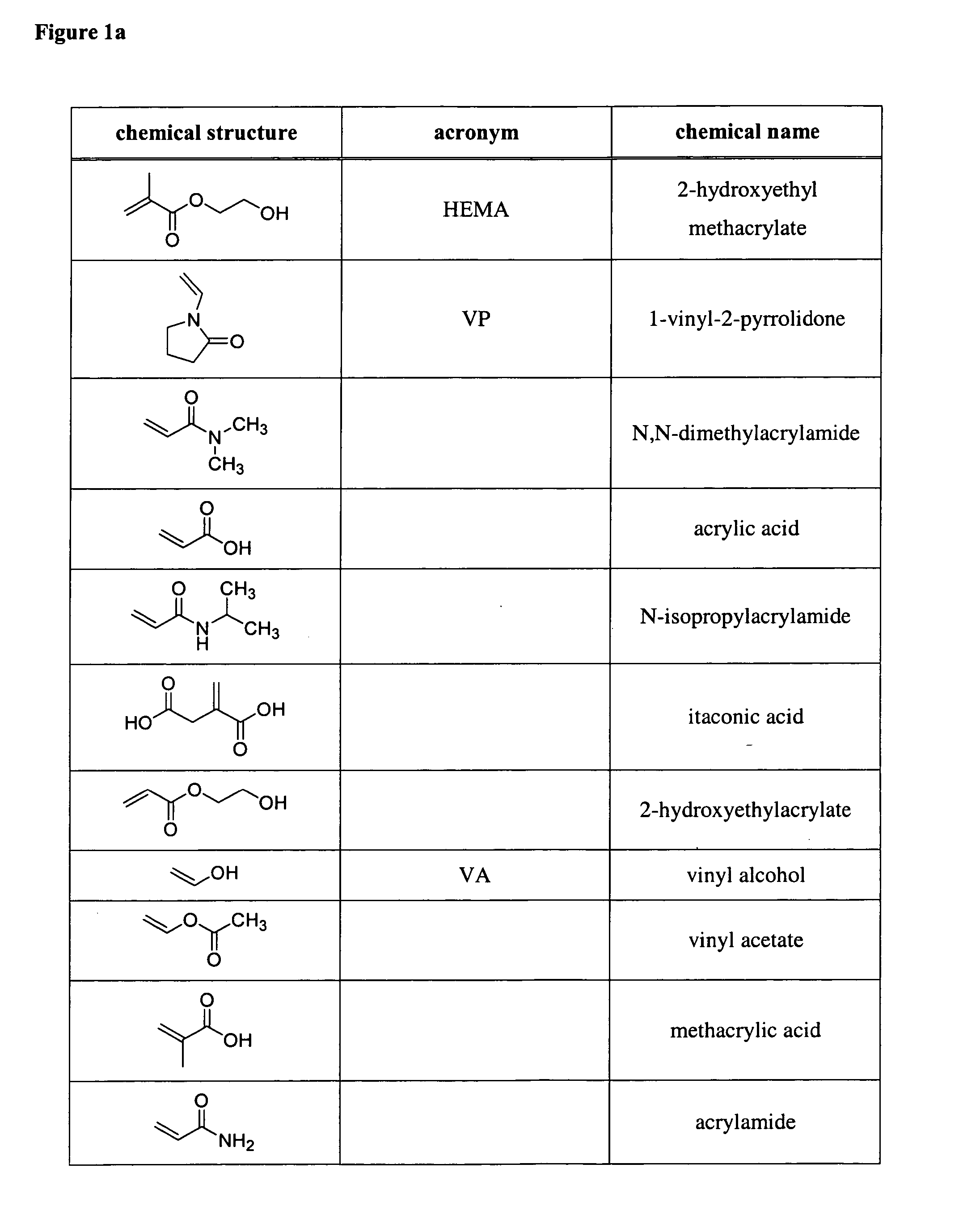
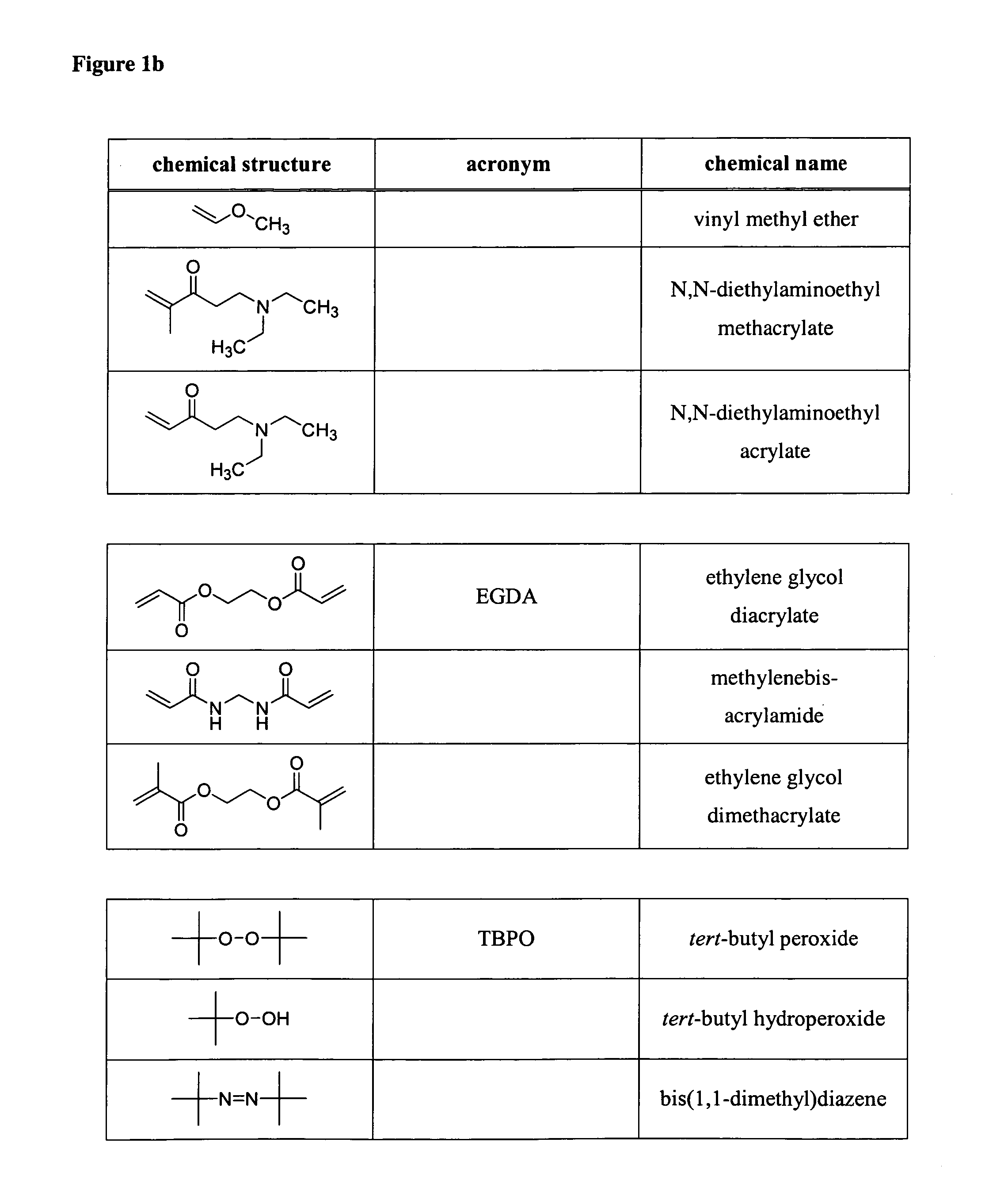
[0485] Preparation of PHEMA-containing Films.

[0486] Two series of films were prepared. For the homopolymer experiments (linear PHEMA, denoted L1 to L5 in Table 3), no EGDA was introduced into the reactor.

TABLE 3Details of Experimental Runs (HEME / EGDA)Partial PressureFlow Rate (sccm)(mTorr)SampleHEMAEGDATBPON2HEMAEGDALinearSeriesL13.0—1.03.0150—L23.5—1.02.5175—L34.0—1.02.0200—L44.5—1.01.5225—L55.0—1.01.0250—Cross-linkedSeriesX14.00.01.02.02000X24.00.51.01.520025X34.01.01.01.020050X44.01.51.00.520075X54.02.01.00.0200100

[0487] The flow rate of HEMA was varied between 3 and 5 sccm in increments of 0.5 sccm, whereas that of TBPO was kept constant at 1 sccm. A patch flow of nitrogen was also introduced into the reactor to keep the total flow rate at 7 sccm. This arrangement ensured the same residence time of 5 s for all experimental runs. For the crosslinking experiments (crosslinked PHEMA, denoted X1 through X5 in Table 3), both the flow rates of HEMA (4 sccm) and TBPO (1 sccm) were k...

example 2b

[0488] Preparation of PVP-containing Films.

[0489] Two series of films were prepared. For the homopolymer experiments (linear PVP, denoted L6 to L10 in Table 4), no EGDA was introduced into the reactor.

TABLE 4Details of Experimental Runs (VP / EGDA)Partial PressureFlow Rate (sccm)(mTorr)SampleVPEGDATBPON2VPEGDALinear Series (500 mTorr)L67.0—1.02.0350.0—L76.5—1.02.5325.0—L86.0—1.03.0300.0—L95.5—1.03.5275.0—L105.0—1.04.0250.0—Cross-linked Series (420 mTorr)X610.00.01.01.0350.00.0X79.50.51.01.0332.517.5X89.01.01.01.0315.035.0X98.51.51.01.0297.552.5X108.02.01.01.0280.070.0

The flow rate of PVP was varied between 5 and 7 sccm in increments of 0.5 sccm, whereas that of TBPO was kept constant at 1 sccm. A patch flow of nitrogen was also introduced into the reactor to keep the total flow rate at 9 sccm. This arrangement ensured the same residence time for all experimental runs. For the crosslinking experiments (crosslinked PVP, denoted X6 through X10 in Table 4), flow rate of PVP was varied...


PUM

PropertyMeasurementUnit
temperaturesaaaaaaaaaa
contact angleaaaaaaaaaa
temperatureaaaaaaaaaa

Abstract

In one embodiment of the invention, iCVD is used to form linear thin films using a radical initiator and an alkene. In another embodiment, iCVD is used to form crosslinked thin films by the addition of a crosslinking agent (e.g., a diacrylate or a dimethyacrylate). The incorporation of a crosslinking agent into the thin films is shown to increase systematically with its partial pressure. In one embodiment, when the crosslinker is EDGA and the monomer is HEMA it results in crosslinked P(HEMA-co-EGDA) copolymer. In another embodiment, when the crosslinker is EDGA and the monomer is VP, it results in crosslinked P(VP-co-EGDA). Disclosed are the effects of crosslinker incorporation on the thermal and the wetting properties of the polymers. The unique swelling properties of these films are also described; certain films of the present invention are hydrogels when soaked in water.

Description

GOVERNMENT SUPPORT [0001] This invention was made with support provided by the National Science Foundation under Grant DMR-9400334; therefore, the government has certain rights in the invention.BACKGROUND OF THE INVENTION [0002] Chemical vapor deposition (CVD) is a one-step, vacuum process, involving no solvents or volatiles. Using CVD, monomers are converted directly to desired polymeric films without the need for purification, drying, or curing steps. Custom copolymers can be created simply by changing the ratio of feed gases to the CVD reactor (Murthy, S. K.; Gleason, K. K. Macromolecules 2002, 35, 1967). CVD allows films of nanoscale thicknesses with macroscale uniformity to be produced and can be applied to complex geometries (Pierson, H. O. Handbook of Chemical Vapor Deposition, 2nd ed.; Noyes Publications: Norwich, N.Y., 1999). CVD can also be used to coat nanoscale features, as there are no surface tension and non-uniform wetting effects that are typically associated with we...

Claims


Application Information

Patent Timeline
Patent Type & Authority Applications(United States)
IPC IPC(8): C08F4/00
CPCC09D4/00B05D1/60
Inventor GLEASON, KAREN K.CHAN, KELVIN
Owner MASSACHUSETTS INST OF TECH
Why Eureka
Try Eureka