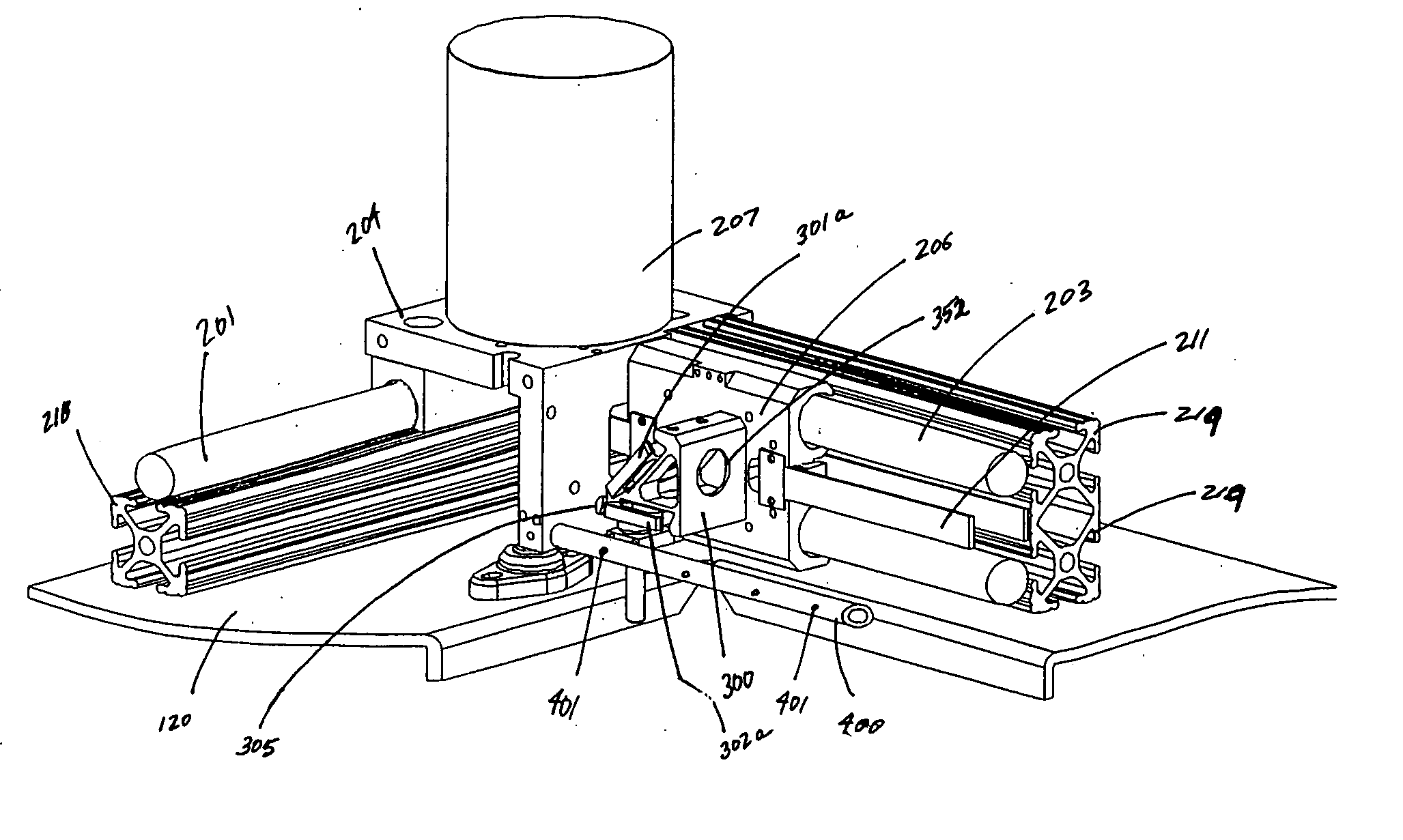
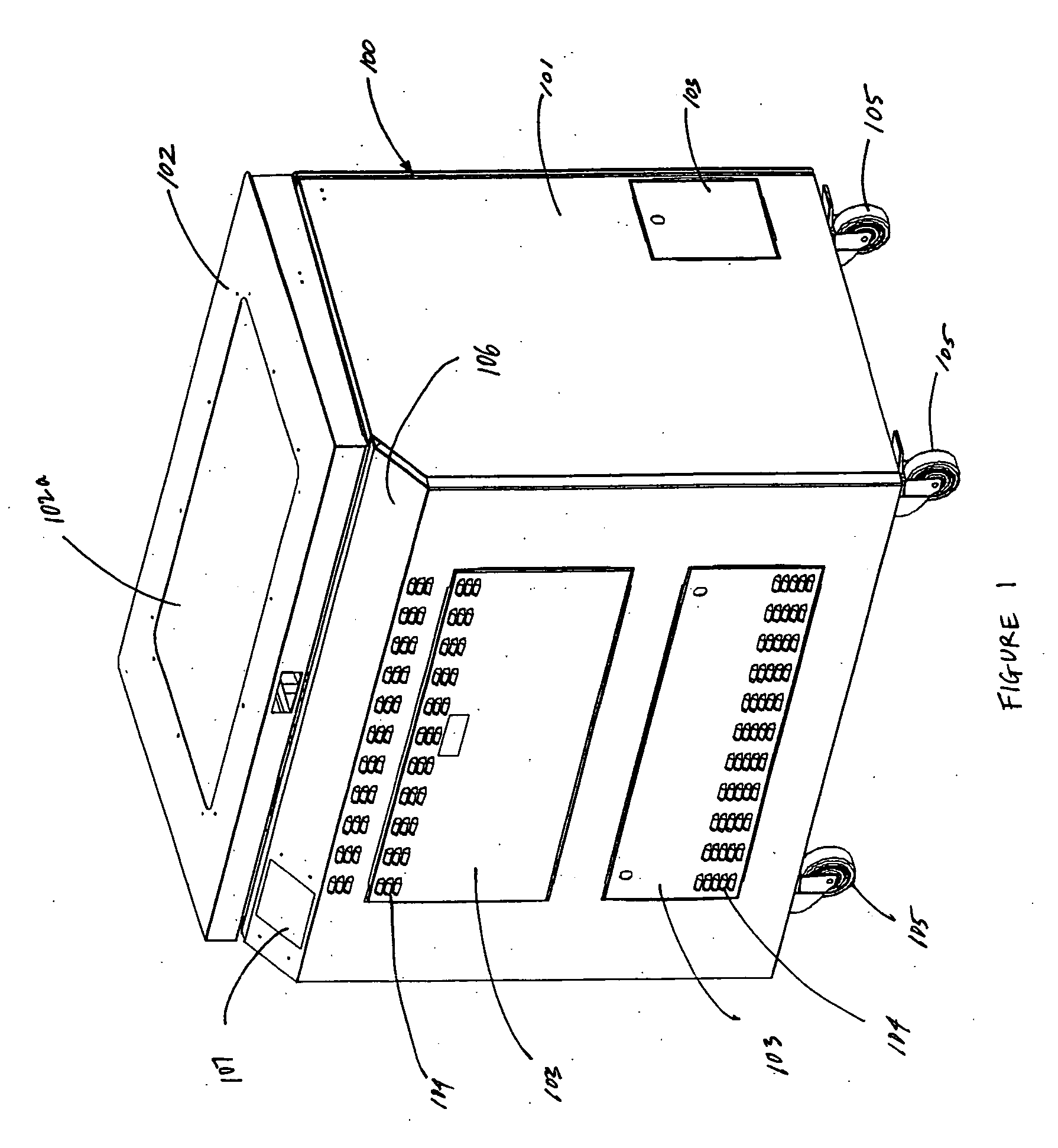
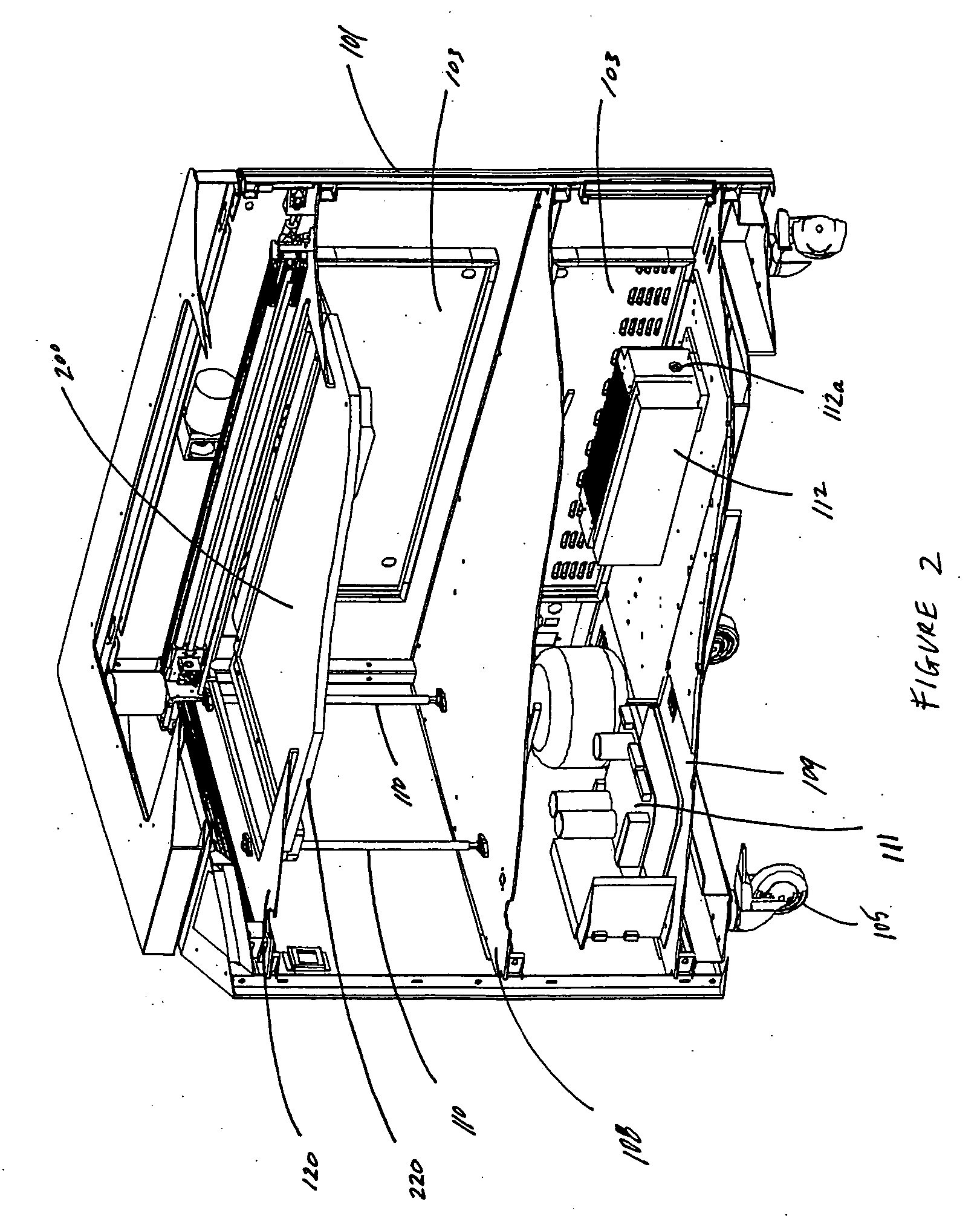
[0012] In the preferred embodiment, the automated laser engraver of the present invention has a substantially flat work surface which is protected by a hinged cover. Said substantially flat work surface effectively defines an x-axis and a y-axis. An automated gantry assembly is mounted in general proximity to said substantially flat work surface. Said gantry assembly comprises first and second elongate rails, oriented parallel to one another, along the y-axis of said work surface. A
third rail, oriented perpendicular to said first and second rails along the x-axis of said work surface, is movably mounted to said first and second rails using traveling bracket members. Said
third rail can be moved to various positions along said parallel first and second rails and, thus, along the y-axis of the work surface. A
carriage assembly, which is movably received on said
third rail, can travel along the length of said third rail between said parallel first and second rails.
[0013] In the preferred embodiment of the present invention, said traveling bracket members utilize non-recirculating
polymer bearings that ride on said first and second rails. Similarly, said
carriage assembly also utilizes such non-recirculating
polymer bearings that ride on said third rail. Said first, second and third rails are hard coated, anodized rails. Said bearings act to push debris (such as from the engraving process, for example) from said rails, thereby reducing cleaning and maintenance requirements for said gantry assembly. Said non-recirculating
polymer bearings riding on said hard coated, anodized rails within the gantry assembly permit the
machine to achieve
high acceleration and engraving speeds of 120 inches per second and greater with low maintenance requirements.
[0014] A first drive mechanism is used to move said first and second traveling brackets (and, accordingly, the third rail) along the length of said first and second rails, respectively. In the preferred embodiment of the present invention, said drive mechanism comprises at least one
stepper servo motor and at least one drive belt. Similarly, a second drive mechanism is used to move said
carriage assembly along said third rail. In the preferred embodiment, said second drive mechanism comprises at least one
stepper servo motor and at least one drive belt. At least one
encoder compensates for drive belt flex and maintains the speed of said first and second traveling brackets, as well as said carriage assembly, at desired levels which improves overall quality of the engraving process. Said at least one
encoder provides information for motion adjustments and belt flex compensation to the applicable
stepper servo motor(s).
[0015] A beam from an engraving laser is aimed at a workpiece being engraved using an optical assembly mounted on said carriage assembly. As said carriage assembly moves to desired locations relative to a workpiece being engraved, said laser beam engraves the surface of said workpiece. In the preferred embodiment,
optics (mirrors and lens) utilized to aim and focus said laser beam are removable for easy cleaning and can be replaced in position without requiring re-alignment.
[0016] Air is conveyed onto the engraving work surface to cool the workpiece and reduce the possibility of fire. In the preferred embodiment, said air flow is supplied through a tube which is mounted at or near said carriage assembly.
Air travels through said tube and passes through a plurality of holes along the length of the tube in the general direction of the area where the laser beam strikes the workpiece. Said tube can be rotated to direct such air flow as desired.
[0018] In the preferred embodiment, a computer touch screen, mounted in a convenient location relative to the laser engraver, permits easy
data input for management of engraving job(s). Said touch screen can control functions such as focus point determination, job setup, job positioning, speed adjustments, job performance data and job preview
zoom. Said computer touch screen also allows an operator to select engraving specifications directly from a host computer's hard drive and run such jobs on the
laser engraving machine. Additionally, in the preferred embodiment, said computer touch screen also allows an operator to determine focus points on a laser table work surface, change operating parameters of the
system, position a job on the engraving table work surface and adjust engraving speeds.

