Insulated rail for electric transit systems and method of making same

Inactive Publication Date: 2007-02-15
METROSHIELD
View PDF39 Cites 17 Cited by
  • Summary
  • Abstract
  • Description
  • Claims
  • Application Information

AI Technical Summary

Benefits of technology

[0006] It is another object of the present invention to provide for a novel and improved rail system which is rugged, durable and comprised of a minimum number of parts.
[0007] It is a further object of the present invention to provide for a novel and improved insulated rail system which is vibration and sound-proof as well as capable of substantially eliminating any corrosion resulting from stray or leakage current and which enables greatly simplified installation over extended distances.
[0008] It is an additional object of the present invention to provide for a novel and improved method of manufacturing insulated rail in a minimum number of steps and which results in the formation of a rubber clad rail assembly.
[0009] A preferred form of the present invention resides in a transportation rail for extension along

Problems solved by technology

This approach has been unsatisfactory particularly from the standpoint of complete vibration and sound-proofing as well as providing the necessary resistance to corrosion resulting from stray electrical current.
Over e

Method used


Image

  • Insulated rail for electric transit systems and method of making same
  • Insulated rail for electric transit systems and method of making same

Examples


Embodiment Construction

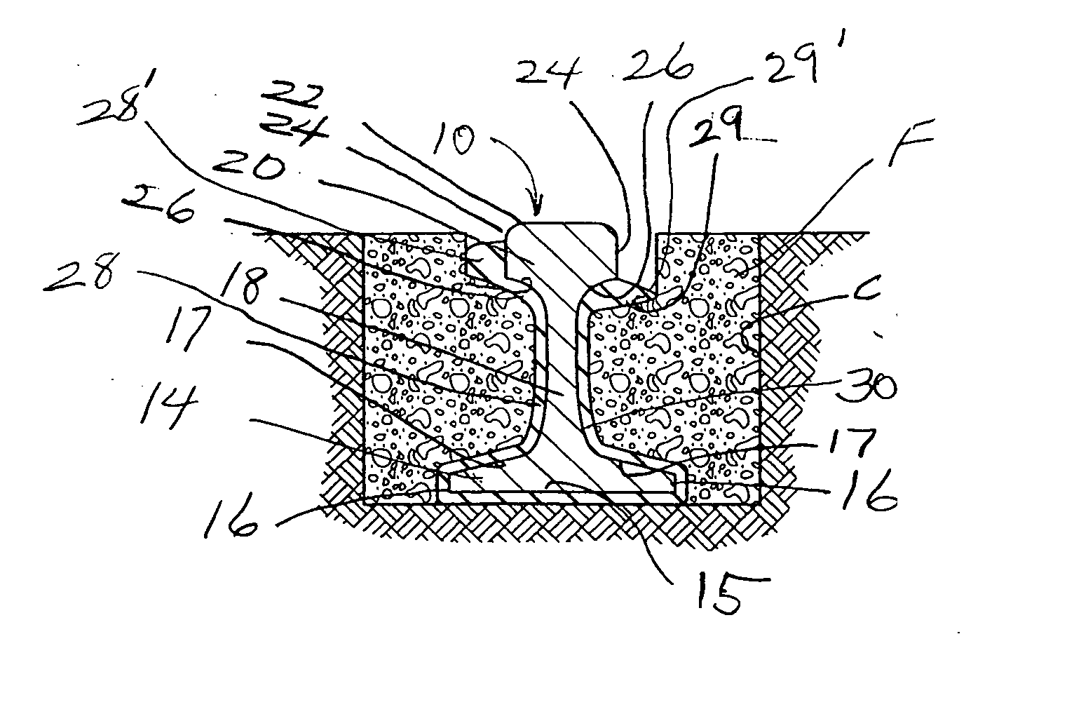
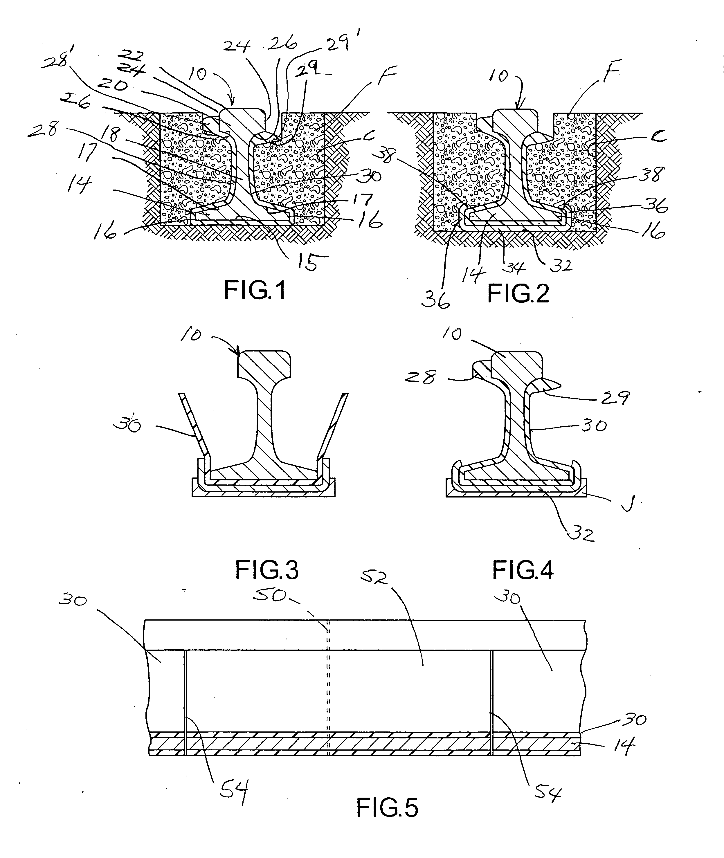
[0017] Referring in more detail to the drawings, FIG. 1 illustrates one preferred form of a composite rail which is made up of a standard rail 10 and a rail cover 12. The rail 10 is of generally I-shaped cross-sectional configuration having a bottom flange 14 provided with a flat undersurface 15 and opposite sides 16 together with sloped upper surfaces 17 which merge into a vertical web portion 18. A top flange 20 has a slightly convex top surface 22 and opposite sides 24 together with sloped undersurfaces 26 which merge into the upper end of the vertical web portion 18. In accordance with conventional practice, the rail may be composed of various grades of steel or aluminum depending upon load requirements. As a setting for the present invention, the rail is composed of steel and is designed with a relatively broad base flange 14 in comparison to the width of the top flange 20.

[0018] In accordance with the present invention, the rail is adapted for use as a railroad track for the ...


PUM


Abstract

A rail cover and support for mounting and insulating the rails of an electric transit system in which the rail cover is vulcanized both to the rail and outer skid support at the manufacturing site prior to delivery to the field and a rail cover completely surrounds both the base flange and web portion of each rail and terminates along the undersides of the top flange. In one form, the upper free ends of the rail cover are increased in thickness to form bumpers along opposite sides of the rail to cushion it against undue shifting or vibration. In fabricating the rail, a sheet dielectric material is vulcanized to the rail with or without a skid plate.

Description

BACKGROUND AND FIELD OF INVENTION [0001] This invention relates to railway systems and more particularly relates to a novel and improved rail adaptable for use in electric transit systems of metropolitan areas. [0002] It has been proposed in the past to utilize resilient pads beneath the lower flanges of railroad rails as well as railroad ties for cushioning the rails and insulating them electrically from the ties and from other underlying structures. In many cases, clamps are employed on opposite sides of the lower flange which are in turn anchored into the railroad ties or rail bed. Also, in some cases an adhesive is interposed between the pad and the rail. [0003] Different considerations are involved in the construction and installation of rails for urban transit systems which are typically employed as a part of electrical transit systems and must be mounted in asphalt or concrete roadways. Instead of a gravel or dirt roadbed the rails are embedded in spaced parallel channels for...

Claims


Application Information

Patent Timeline
IPC IPC(8): E01B21/00
CPCE01B21/00E01B19/003
Inventor GRAY, HAROLD W. JR.
Owner METROSHIELD
Why Eureka
Try Eureka