Field sequential light source modulation for a digital display system

ield sequential technology, applied in the field of image processing and modulation system of a digital display system, can solve the problems of reducing magnification, difficult to achieve acceptable visual quality, and changing display characteristics, so as to improve image consistency, enhance color gamut, and improve image quality

Active Publication Date: 2007-02-15
SAMSUNG ELECTRONICS CO LTD
View PDF16 Cites 412 Cited by
  • Summary
  • Abstract
  • Description
  • Claims
  • Application Information

AI Technical Summary

Benefits of technology

[0020] The present invention provides an apparatus and method for performing image processing that controls both the image modulator and the colored light sources to enhance display quality.
[0023] An exemplary Flat Panel Display system has a patterned array of red, green and blue LEDs as the back light and an LCD panel as the image modulator. The LEDs are individually controlled and illuminate the LCD panel, which is much higher resolution than the number of LEDs. Depending on its position on the panel, each triplet of LEDs affect a block of LCD image pixels. The Display Output Processing (DOP) for this exemplary system field sequences the image modulator and the colored light sources. The resulting display has improved image consistency, enhanced color gamut, and higher dynamic range, and is better able to portray high motion content.

Problems solved by technology

Manufacturing FPDs requires special processing steps and it is often difficult to achieve acceptable visual quality in terms of consistence across the entire area of the display.
Besides being a yield issue for new displays, display characteristics can change over operating conditions and over the lifetime of the display.
Radial distortion includes barrel distortion, where image magnification decreases towards the corners, and pin cushion distortion, where the magnification increases towards the corners.
Lens related distortions including radial distortion can cause image deformation.
Distortion can also result from non-flat screens or the Earth's magnetic field.
Shortening the projection path, often done to thin a rear projection system, also increases distortion.
Each color component of the pixels mapped to the screen display pixels may transfer non-uniformly where some pixels end up too bright and others end up not bright enough.
Similarly for LED backlit FPDs, the spacing and positioning of the LEDs may cause non-uniform brightness patterns where the image modulator pixels closer to the LEDs appear brighter than the image modulator pixels further from the LEDs.
Since color filters typically operate by filtering out wavelengths from a white light source, some lumen efficiency is lost by using color filters.
However, because of the nature of LCD image modulator pixels, the transitions for modulating light intensities are not purely digital, and are not necessarily linear.
The light sources for a modulator based system may not be able to achieve the desired brightness or accurately and uniformly reproduce the intended color gamut.
Different modulator pixel positions on the screen may be affected by the light sources differently, causing a display of non-uniform color and brightness.

Method used


Image

  • Field sequential light source modulation for a digital display system
  • Field sequential light source modulation for a digital display system
  • Field sequential light source modulation for a digital display system

Examples


first embodiment

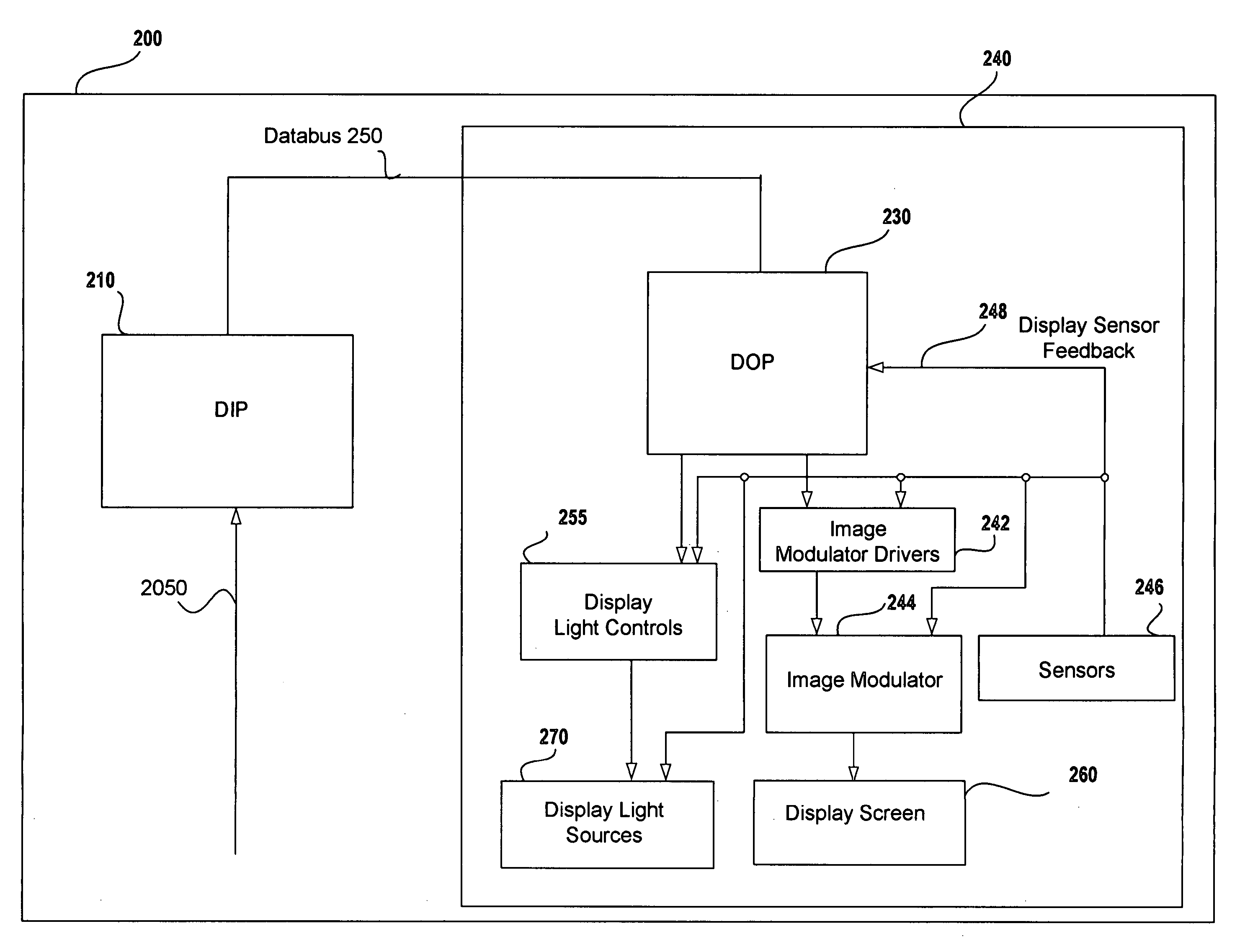
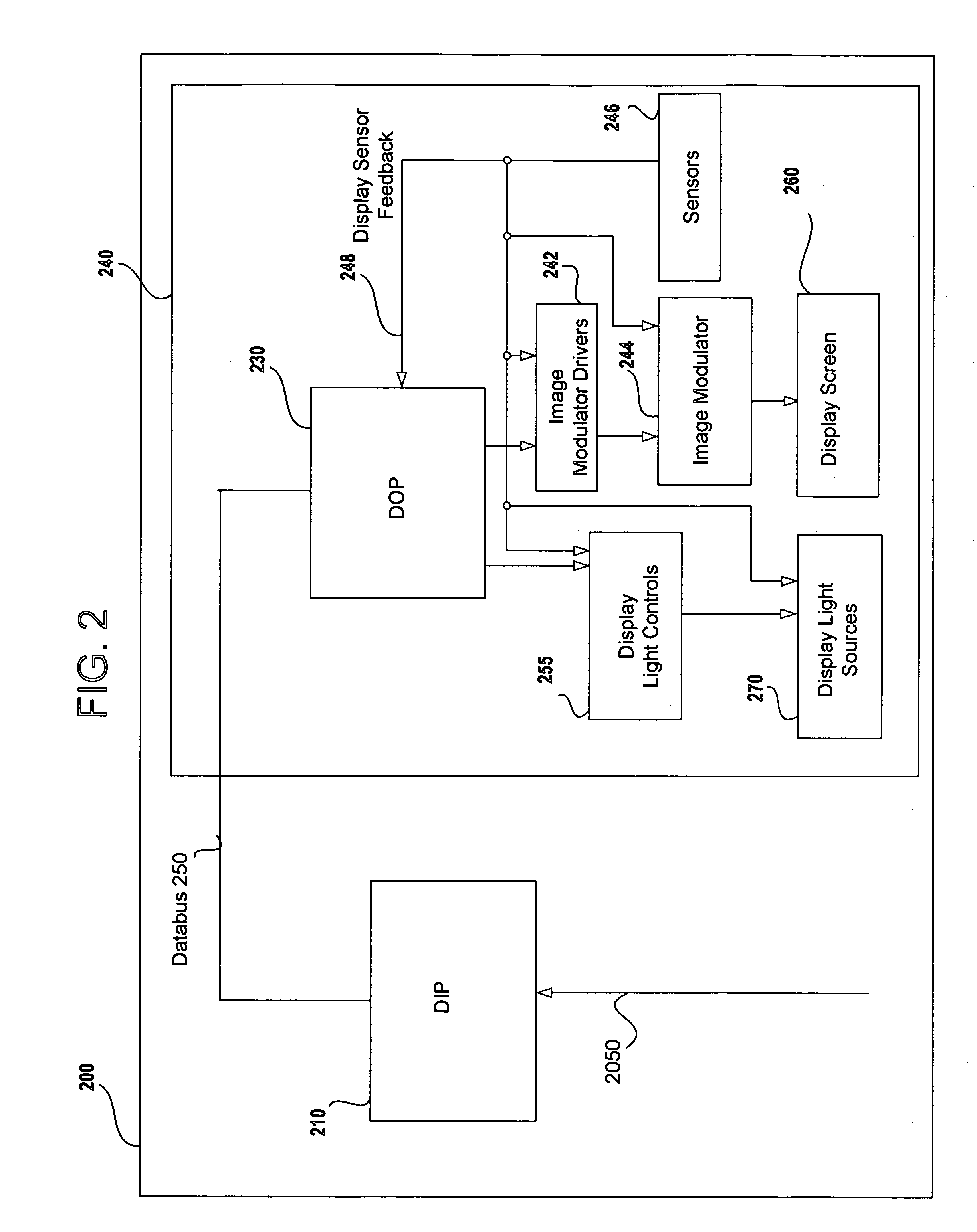
[0150] In a first embodiment, the LED configuration of FIG. 6 is combined with an image modulator 244 that includes a color filter. The image modulator typically has one independently controlled sub pixel for each color such that a display with 1600 columns of pixel triads (R, G, B) has 4800 actual pixel sites that are controlled by the DOP 230 and image modulator drivers 242. Since the image modulator includes color filters, a white light source is all that is required. The white light may be provided by white LEDs, by colored LEDs or some combination where changes in the light color can be used to affect the color temperature. In a more sophisticated system, the image data can be used to control the LEDs to affect the pixel colors for the display image either across the entire image or on a sub image basis. The individual rows of LEDs may be controlled all at once or sequenced from top to bottom matching the display information scanned via the image modulator drivers 242 into imag...

second embodiment

[0152] A second embodiment where the image modulator 244 does not include a color filter uses the LED configuration of FIG. 6 in a field sequential color mode. The effective display image is determined by the three (R, G, B) sequential color image fields. The resolution of the image modulator, since it only needs to support one color at a time, is typically one third that of the equivalent color filtered image modulator. Similarly, the number of pixels required to be scanned into the image modulator for each color is one third of the total. Depending on the speed and configuration of both the image modulator 244 and the image modulator drivers 242, the time to scan in each color field image may or may not be lower than scanning the complete image. Temporal Gamma Processing across the color fields may be used to achieve more accurate and higher scanning rates. The timing of the color fields within a frame and between frames may be varied along with the flashing intervals to avoid col...


PUM


Abstract

A digital display system consists of an image modulator and multiple light modulators. An image processing system processes an incoming data stream, scans processed data to an image modulator and controls for the light modulators. Other user inputs and sensors are used to affect the processing and controls. The timing for scanning the processed data into the image modulators is controlled along with the intensity and wavelength of the light modulators. The display system may implement a spatial and temporal image processing, digital shutter controls, rolling shutter controls, sequential color output, adaptive dynamic sensor feedback, frame rate matching, motion compensated field sequencing and a variety of other techniques to produce a high quality display output. The resulting display has improved image consistency, enhanced color gamut, higher dynamic range and is better able to portray high motion content.

Description

[0001] This application is a Continuation-in-Part of U.S. application Ser. No. 11 / 255,353 filed Oct. 21, 2005, which is a Continuation-in-Part of U.S. application Ser. No. 11 / 158,476 filed Jun. 20, 2005.BACKGROUND OF THE INVENTION [0002] 1. Field of the Invention [0003] The present invention relates generally to an image processing and modulation system for a digital display system, and more particularly to performing field sequential lighting control along with advanced image processing and image modulation to produce high-quality output images. [0004] 2. Discussion of Prior Art [0005] The many types of Flat Panel Display (FPD) technologies include Active Matrix Liquid Crystal Displays (AMLCDs) also referred to as Thin Film Transistor displays (TFTs), silicon Reflective LCDs (si-RLCDs), Liquid Crystal On Silicon (LCOS), ferroelectric displays (FLCs), Field Emission Displays (FEDs), Carbon Nanotube based Nano Emissive Displays (NEDs), ElectroLuminescent Displays (ELDs), Light Emitti...

Claims


Application Information

Patent Timeline
Patent Type & Authority Applications(United States)
IPC IPC(8): G03B21/00
CPCG03B21/00G03B21/206G03B21/26G09G3/3413G09G3/342G09G2310/0235G09G2310/024G09G2320/041G09G2320/0666G09G2360/144G09G2360/145H04N5/7416H04N9/312H04N9/3155H04N9/3197G03B21/2013G03B21/2033G03B21/14G03B21/005G09G3/03G09G2320/045G09G3/32G09G3/20G02F1/133
Inventor MARGULIS, NEAL D.
Owner SAMSUNG ELECTRONICS CO LTD
Why Eureka
Try Eureka