Ceramic material composition, ceramic substrate, and nonreciprocal circuit device

Active Publication Date: 2007-02-15
MURATA MFG CO LTD
View PDF7 Cites 8 Cited by
  • Summary
  • Abstract
  • Description
  • Claims
  • Application Information

AI Technical Summary

Benefits of technology

[0020] A ceramic material composition according to the present invention can be sintered at a low temperature of 1,000° C. or lower; hence, the ceramic material composition can be co-fired with a metal, such as Ag or Cu, having a satisfactory conductivity. In a ceramic substrate having a multilayer structure in which a plurality of ceramic layers are laminated, the above-described metal can be used as a material for a conductor disposed in the ceramic substrate.
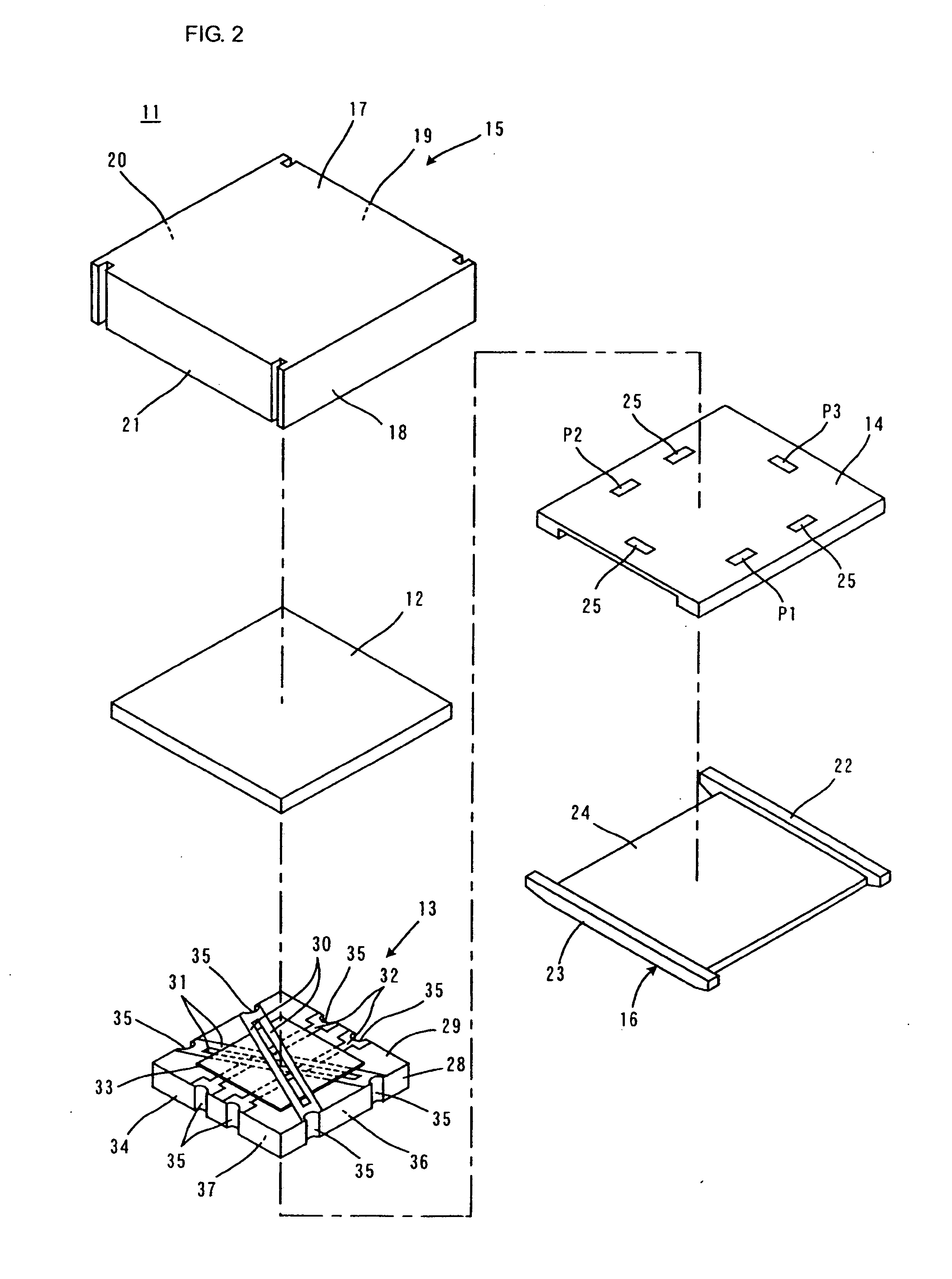
[0021] A sintered body obtained by firing the ceramic material composition according to the present invention has a relatively high dielectric constant. Thus, for example, with respect to an isolator, when the sintered body of the ceramic material composition according to the present invention is used as a material for constituting a ceramic substrate used in the isolator, it is possible to reduce the area of the ceramic substrate to ⅔ to ½ of that of a known ceramic substrate.
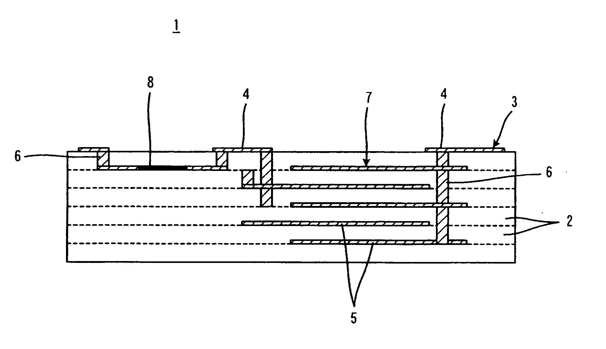
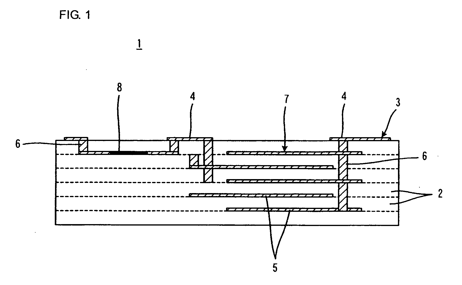
[0022] In the ceramic material composition according to the present invention, the borosilicate glass composition need not contain an alkali metal such as Li; hence, it is possible to avoid the problem of a decrease in resistance characteristics due to the reaction of the alkali metal with a resistive material constituting a resistor. Therefore, the ceramic material composition can be advantageously used as a material for forming a ceramic substrate containing a resistor, and specifically, a ceramic substrate containing a resistor included in a nonreciprocal circuit device such as an isolator.
[0023] To surely achieve the effect described above, when the borosilicate glass composition contains at least one compound selected from Li2O, Na2O, and K2O, the content of the at least one compound is preferably less than about 0.5 percent by weight.
[0024] When the ceramic substrate according to the present invention having the ceramic layer, i.e., a first ceramic layer, composed of a sintered body of the ceramic material composition according to the present invention has a second ceramic layer having a dielectric constant of about 10 or less or has a second ceramic layer composed of a sintered ceramic body containing about 26 to 65 percent by weight of a CaO—Al2O3—B2O3—SiO2 glass composition and about 35 to 74 percent by weight of alumina, the following effects are expressed.
[0025] The first ceramic layer has a high dielectric constant, and the second ceramic layer has a low dielectric constant. Therefore, when a conductor mainly for wiring is disposed with respect to the second low-dielectric-constant ceramic layer, and an element, such as a capacitor or a filter, is formed with respect to the first high-dielectric-constant ceramic layer, it is possible to reduce the size of the ceramic substrate.
[0027] Furthermore, since the first and second ceramic layers contain glass components, it is possible to perform sintering at a relatively low temperature. When firing is performed at a temperature at which the first and second ceramic layers sinter while a constrained layer containing an inorganic material that does not sinter at a temperature at which the first and second ceramic layers sinter is disposed on at least one main surface of a green ceramic substrate, it is possible to suppress the shrinkage in the direction of the main surface by virtue of the constrained layer. As a result, it is possible to produce a ceramic substrate with high dimensional accuracy.

Problems solved by technology

However, it has been found that when the ceramic material composition described in Patent Document 1 is used to produce a ceramic substrate included in the above-described nonreciprocal circuit device, the resistance characteristics of a resistor in the ceramic substrate disadvantageously decreases.

Method used


Image

  • Ceramic material composition, ceramic substrate, and nonreciprocal circuit device
  • Ceramic material composition, ceramic substrate, and nonreciprocal circuit device
  • Ceramic material composition, ceramic substrate, and nonreciprocal circuit device

Examples


experimental example 1

[0083] 1. Production of Ceramic Composition

[0084] To produce a BaO—TiO2—ReO3 / 2 ceramic composition, powders of BaCO3, TiO2, Nd2O3, Pr2O3 and Sm2O3 were weighed so as to achieve contents of BaCO3, TiO2, ReO3 / 2 and the like shown in Table 1, and then the weighed powders were mixed. The resulting material powder mixture was calcined at 1,150° C. for 1 hour. Then, the resulting calcine was pulverized.

[0085] In this way, ceramic compositions S1 to S10 shown in Table 1 were obtained.

TABLE 1Type ofceramicBaOTiO2ReO3 / 2S11358Nd: 10, Sm: 19S22555Nd: 20S3575Nd: 20S4265Nd: 33S51050Nd: 40S61862Nd: 20S7865Nd: 27S8852.5Nd: 39.5S91358Sm: 29 S101358Pr: 6, Sm: 23

(unit: mol %)

[0086] 2. Production of Glass Composition

[0087] To produce a borosilicate glass composition, powders of CaO, MgO, SrO, BaO, Al2O3, B2O3, SiO2, Li2O, Na2O, K2O and PbO were weighed so as to achieve contents shown in Table 2, and then the weighed powders were sufficiently mixed. The resulting material powder mixture melted at...

experimental example 2

[0115] In Experimental Example 2, a ceramic material composition was produced with ceramic composition S1 shown in Table 1 and glass composition G1 shown in Table 2, as shown in Table 5, and then a sintered body of the ceramic material composition was produced in the same way as in Experimental Example 1, except that the contents of the ceramic composition, alumina, and the glass composition were changed.

TABLE 5CeramicGlasscompositionCeO2compositionAmountAluminaparts byAmountSampleType[wt %][wt %]weightType[wt %]33S15.040.00.3G155.034S110.040.00.3G150.035S145.010.00.3G145.036S155.000.3G145.037S145.05.00.3G150.038S142.010.00.3G148.039S112.040.00.3G148.040S110.050.00.3G140.041S145.025.00.3G130.042S140.020.00.3G140.043S123.012.00.3G165.044S120.010.00.3G170.0

[0116] Next, each sample shown in Table 5 was evaluated for dielectric constant, Q-value, the temperature coefficient of capacitance, and reliability in a PCT in the same way as in Experimental Example 1. Furthermore, in Experimen...

experimental example 3

[0124] In Experimental Example 3, as shown in Table 7, a ceramic material composition was produced with ceramic composition S1 shown in Table 1 and glass composition G1 shown in Table 2, and then a sintered body of the ceramic material composition was produced in the same way as in Experimental Example 1, except that the contents of the ceramic composition S1 and CeO2 were changed and, in specific samples, CaTiO3 was added.

TABLE 7CeramicGlasscompositionCeO2compositionAmountAluminaparts byCaTiO3AmountSampleType[wt %][wt %]weight[wt %]Type[wt %]45S134.018.000G148.046S134.018.03.00G148.047S134.018.05.00G148.048S129.018.00.35.0G148.049S114.018.00.320.0G148.050S14.018.00.330.0G148.0

[0125] Next, each sample shown in Table 7 was evaluated for dielectric constant, Q-value, temperature coefficient of capacitance, and reliability in a PCT in the same way as in Experimental Example 1. Table 8 shows the results.

TABLE 8TemperatureDielectriccoefficientconstantQf(TCC)ReliabilitySample(ε)[GHz][...


PUM

PropertyMeasurementUnit
Timeaaaaaaaaaa
Percent by massaaaaaaaaaa

Abstract

A ceramic material composition advantageously used as a material for a ceramic substrate containing for example a resistor such as an isolator disposed therein. includes about 10 to 45 percent by weight of a BaO—TiO2—ReO3 / 2 ceramic composition, the ceramic composition being represented by xBaO-yTiO2-zReO3 / 2 (wherein x, y, and z each represent mole percent, 8≦x≦18, 52.5≦y≦65, and 20≦z≦40, and x+y+z=100; and Re represents a rare-earth element); about 5 to 40 percent by weight of alumina; and about 40 to 65 percent by weight of a borosilicate glass composition containing about 4 to 17.5 percent by weight of B2O3, about 28 to 50 percent by weight of SiO2, 0 to about 20 percent by weight of Al2O3, and about 36 to 50 percent by weight of MO (wherein MO represents at least one compound selected from CaO, MgO, SrO and BaO), wherein the total content of the BaO—TiO2—ReO3 / 2 ceramic composition and alumina is about 35 percent by weight or more.

Description

[0001] This is a continuation of application Serial No. PCT / JP2005 / 016900, filed 14 Sep. 2005.TECHNICAL FIELD [0002] The present invention relates to a ceramic material composition, a ceramic substrate including the ceramic material composition, and a nonreciprocal circuit device including the ceramic substrate. In particular, the present invention relates to the improvement for increasing the dielectric constant of a sintered body obtained by sintering the ceramic material composition. BACKGROUND ART [0003] The present invention is associated with nonreciprocal circuit devices, such as isolators and circulators. Such nonreciprocal circuit devices are now required to have a smaller size. The ability to achieve a reduction in the size of the nonreciprocal circuit device depends on the ceramic substrate used therein. The ceramic substrate in the nonreciprocal circuit device may include a capacitor and a resistor. For example, when the device is used in a high frequency range of 800 MH...

Claims


Application Information

Patent Timeline
IPC IPC(8): C04B35/468
CPCC03C3/064H01G4/129C03C14/004C04B35/462C04B35/468C04B2235/3208C04B2235/3215C04B2235/3217C04B2235/3224C04B2235/3229C04B2235/3236C04B2235/36C04B2235/6025C04B2235/96H01G4/1218C03C3/091C04B35/46C04B35/03C04B35/14C04B35/10
Inventor SUGIMOTO, YASUTAKAOHGA, SATOSHIMURATA, TAKAKI
Owner MURATA MFG CO LTD
Why Eureka
Try Eureka