Fluorescent member, its manufacturing method, and light-emitting apparatus

a technology of fluorescence and manufacturing method, applied in the field of fluorescent members, can solve the problems of low heat resistance, low thermal conductivity of resin (the matrix), and special problems, and achieve satisfactory fluorescent properties and thermal conductivity. good

Active Publication Date: 2022-09-20
KANAGAWA INST OF IND SCI & TECH
View PDF11 Cites 0 Cited by
  • Summary
  • Abstract
  • Description
  • Claims
  • Application Information

AI Technical Summary

Benefits of technology

[0027]According to the present invention, it is possible to provide a fluorescent member having both a satisfactory thermal conductivity and a satisfactory fluorescent property without requiring a high-temperature sintering process (a high-temperature process at a temperature higher than 250° C.), and to provide a method for manufacturing such a fluorescent member and a light-emitting apparatus using such a fluorescent member.

Problems solved by technology

However, such a fluorescent member tends to have a high temperature due to heat generated from the light-emitting diodes, which are the primary light source, and heat caused by the loss in energy conversion in the excitation-to-light-emission process in the fluorescent member, thus causing a problem that the resin (the matrix) having a low thermal conductivity and a low heat resistance degrades.
This problem becomes particularly serious when high-power LEDs or high-power lasers are used.

Method used


Image

  • Fluorescent member, its manufacturing method, and light-emitting apparatus
  • Fluorescent member, its manufacturing method, and light-emitting apparatus
  • Fluorescent member, its manufacturing method, and light-emitting apparatus

Examples


example

[0091]The present invention will be described hereinafter in a more detailed manner by using examples. However, the present invention is not limited to the below-described embodiments.

experiment example

[Experiment Example A] (Densification of Matrix Part)

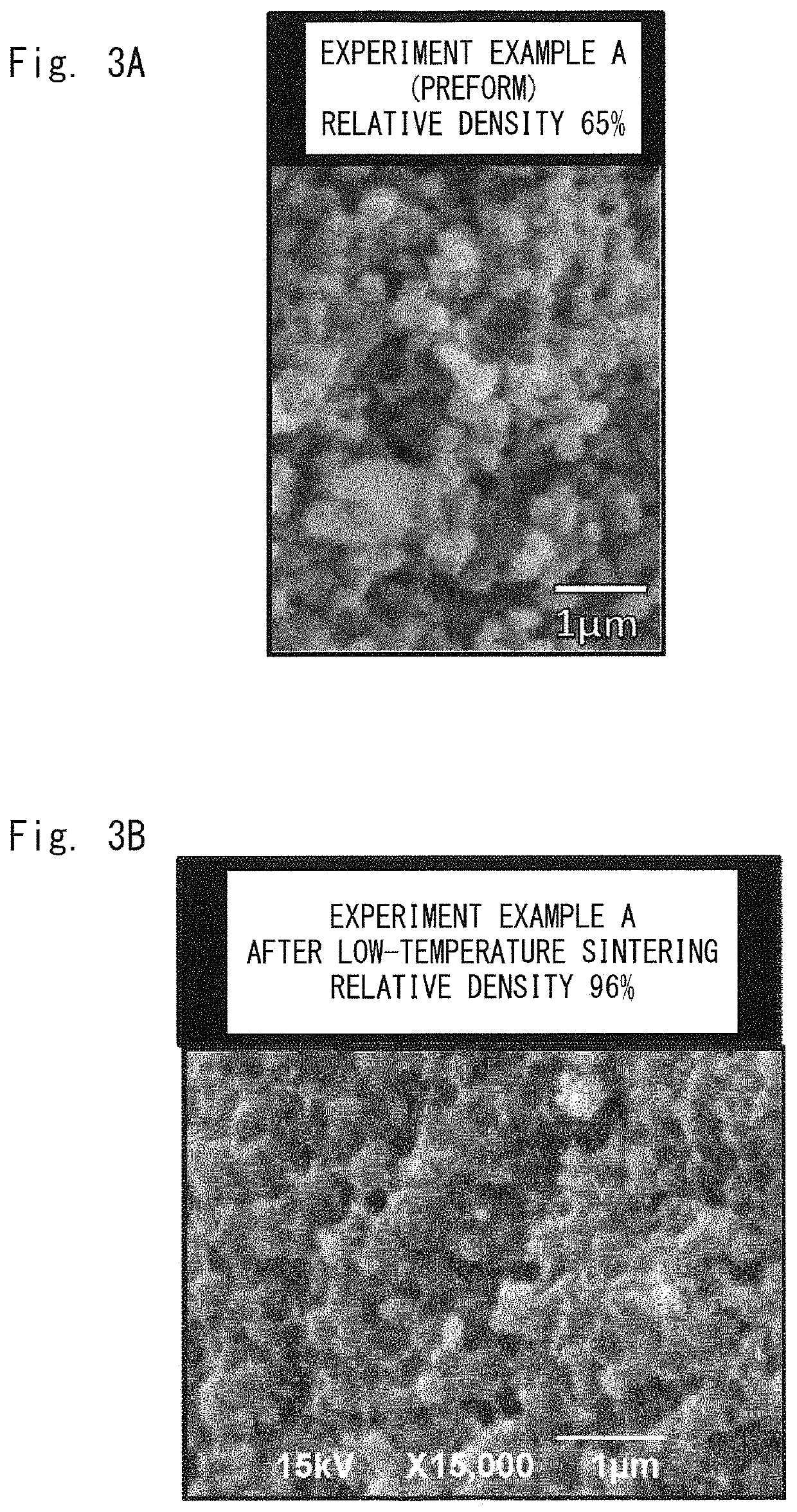
[0092]A mixture of matrix powders was obtained by weighing DISPERMAG (Registered Trademark) TN-1 (average particle diameter 0.57 μm, manufactured by Tateho Chemical Industries Co., Ltd.) and PUREMAG (Registered Trademark) FNM-G (average particle diameter 0.54 μm, manufactured by Tateho Chemical Industries Co., Ltd.) as raw material MgO powders so that their mass ratio became 7:3, and mixing them by using a mixer. A pre-molded body was obtained by charging 1 g of this mixture of the matrix powders into a cylindrical stainless steel mold having a diameter of 15 mm, and performing primary molding at 50 MPa for 30 seconds by using a uniaxial pressure molding machine (Product name: Hydraulic Shop Press, manufactured by Woodward Fab).

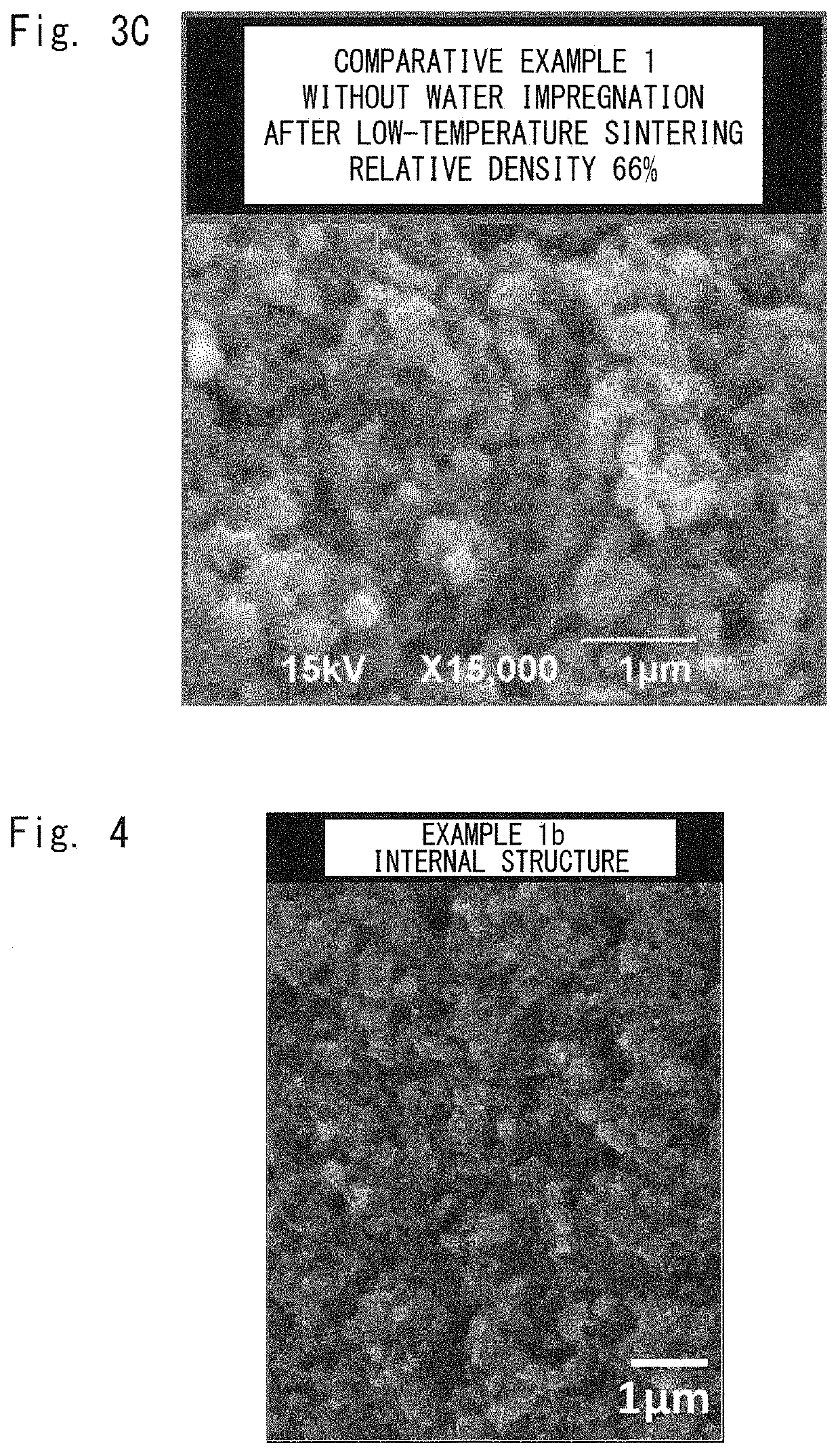
[0093]Next, a preform was obtained by applying an isostatic pressure of 1,000 MPa at a room temperature for one minute. The relative density of the preform was 65%. The preform was impregnated with 10 mass ...

example 1a

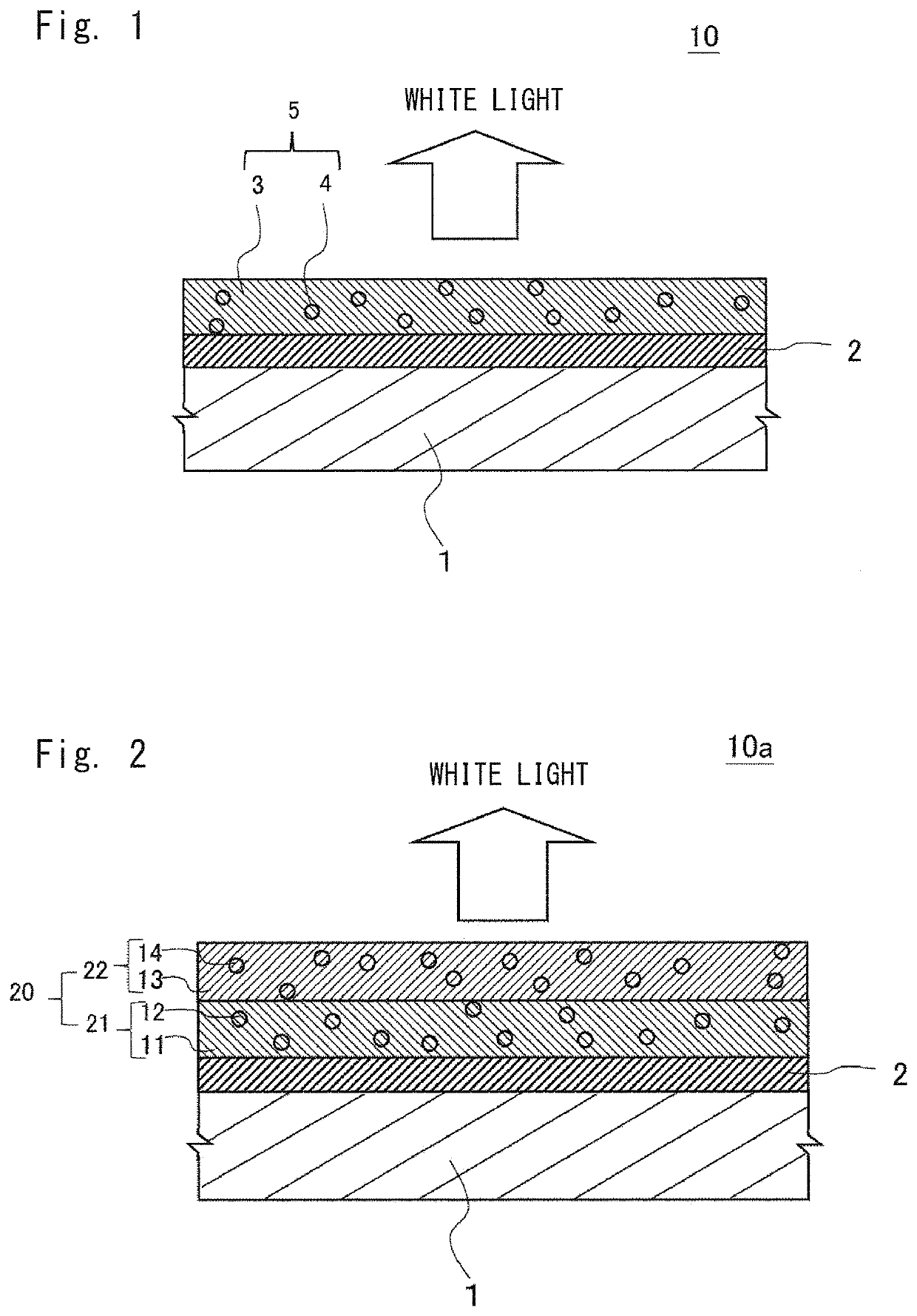
[0095]A red phosphor (CASN manufactured Sialon Co., Ltd.) was further added as phosphor particles in the mixture of the matrix powders of the Experiment Example A. A phosphor particle-containing mixture was obtained by sufficiently mixing the raw-material powder and the phosphor particles in a mortar so that their volume ratio became 99:1. A preform was formed by charging 1 g of this phosphor particle-containing mixture into a mold in a manner similar to that for the Experiment Example A and performing similar processes under similar conditions to those in the Experiment Example A, and then a fluorescent member, which was a sintered body, was obtained therefrom. The relative density of the preform was 65%, and the relative density of the fluorescent member was 92%.


PUM

PropertyMeasurementUnit
thermal conductivityaaaaaaaaaa
mass ratioaaaaaaaaaa
temperatureaaaaaaaaaa

Abstract

A fluorescent member according to present invention is composed of a sintered body for wavelength conversion containing a matrix containing magnesium oxide and magnesium hydroxide as main components, and phosphor particles dispersed in the matrix. A thermal conductivity of the fluorescent member is preferably 5 W / (m·K) or higher. A fluorescent member having both a satisfactory thermal conductivity and a satisfactory fluorescent property is provided without requiring a high-temperature sintering process (a high-temperature process at a temperature higher than 250° C.). Further, a method for manufacturing such a fluorescent member and a light-emitting apparatus using such a fluorescent member are provided.

Description

TECHNICAL FIELD[0001]The present invention relates to a fluorescent member and a method for manufacturing a fluorescent member. Further, the present invention relates to a light-emitting apparatus including a semiconductor light-emitting element and the aforementioned fluorescent member.BACKGROUND ART[0002]Light-emitting apparatus equipped with semiconductor light-emitting elements such as light-emitting diodes (LEDs: Light Emission Diodes) or laser diodes (LDs: Laser Diodes) are excellent in low power consumption and long life, and are used for lighting apparatuses, backlights for liquid crystal display devices, or light sources of laser devices. Among such LEDs, white LEDs have been widely and increasingly used as alternative lighting elements to fluorescent lamps.[0003]For such white LEDs, a technique for emitting white light by combining a light-emitting diode serving as a primary light source with a fluorescent member has been known. As such a fluorescent member, a molded objec...

Claims


Application Information

Patent Timeline
Patent Type & Authority Patents(United States)
IPC IPC(8): C09K11/77C09K11/02H01L33/50C04B35/645C04B35/053C04B41/45C04B41/50C09K11/08
CPCC09K11/77348C04B35/053C04B35/645C04B41/4578C04B41/502C09K11/02H01L33/502C04B2235/30C04B2235/3206C04B2235/3852C04B2235/5436C04B2235/5454C04B2235/616C04B2235/66C04B2235/77C09K11/0883C09K11/64G02B5/20H01L33/501H01L2933/0041
Inventor TATAMI, JUNICHITAKAHASHI, EMITAKAHASHI, TAKUMA
Owner KANAGAWA INST OF IND SCI & TECH
Why Eureka
Try Eureka