Protector for a fibre-optic catheter

a protection device and fibre-optic catheter technology, applied in the field of physical engineering, can solve the problems of high cost, high cost, and economic impracticality of disposable optical probes, and achieve the effects of improving the safety and efficiency of use, cleaning and disinfecting and/or sterilizing, and improving the safety of us

Inactive Publication Date: 2007-02-15
IMALUX CORP
View PDF1 Cites 28 Cited by
  • Summary
  • Abstract
  • Description
  • Claims
  • Application Information

AI Technical Summary

Benefits of technology

[0008] The present invention is directed to a protector design for an optical fiber probe that ensures an effective optical contact between an end face of a distal part of an optical fiber probe and a biological tissue. The protector of the invention provides a temporary mechanical contact between the protector window and the biological tissue, it is technologically effective and can be implemented without using complex design solutions.

Problems solved by technology

However, making the optical probe disposable might be economically impractical due to its high cost.
Cleaning and disinfecting and / or sterilizing the probe prior to using it for a patient is time consuming, requires special equipment and shortens the time of effective use and the service life of the probe.
Nevertheless, there exists an air gap between the inner surface of the protector window and the end face of the distal part of the optical fiber probe due to rigidity of the material the protector window is made of and unevenness of its surface.
For that reason the optical contact between the end face of the distal part of the optical fiber probe and the rigid protector window is not efficient and hence the optical contact between the end face of the distal part of the optical fiber probe and the biological tissue is not effective too.
However, experience has shown that when using this protector power loses of the optical radiation may be considerably high.
That leads to additional optical losses and artifacts in measurements provided by an optical device such as, for example, a device for optical coherence tomography.
It is evident that the use of a polyurethane membrane does not eliminate the unallowable air gap between the membrane and the end face of the distal part of the optical fiber probe.
However, this procedure is time consuming and fairly laborious, especially taking into account that the diameter of the protector may be 3 mm or less.
Applying this fluid to the inner surface of the output window in the course of its manufacturing is impractical since it is impossible to retain the fluid on the surface in storage and shipping.
A disadvantage of this protector is its implementation complexity subject to the fact that the protector must be equipped with a fluid supply and with a device for delivering fluid into the chamber.
The later, especially when using the protector for a miniature optical fiber probe with a diameter of about 3 mm or less, intended for endoscopic studies, is an extremely complicated task.
Besides, the requirements for durability and pliability of the material the fluid chamber is made of are fairly severe, as well as for the material of the inflation channel.
Another disadvantage of this prior art protector is that it does not allow to increase the friction coefficient between the outer surface of the protector window and the biological tissue.

Method used


Image

  • Protector for a fibre-optic catheter
  • Protector for a fibre-optic catheter

Examples


Embodiment Construction

[0048] The protector shown in FIG. 1 operates as follows.

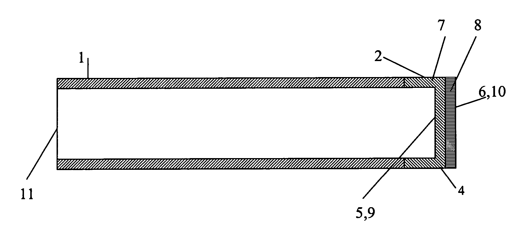
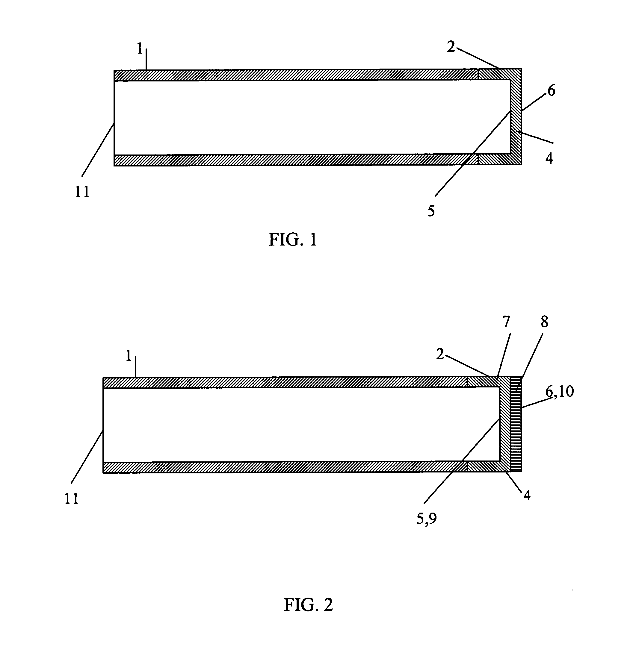
[0049] An optical fiber probe (not shown in the drawing) is placed inside a sheath 1, which is designed to allow for the optical fiber probe to be placed inside of it. A closed distal end 2 of the sheath 1 is made as a window 4, which is at least partially, optically transparent. An end face of a distal part of the optical fiber probe is brought into contact with an inner surface 5 of the window 4. The inner surface 5 of the window 4 is designed capable of forming a temporary adhesive contact with the end face of the distal part of the optical fiber probe under a pressure of an axial force exerted on the optical fiber probe placed inside the sheath 1. An outer surface 6 of the protector window 4 is designed capable of forming a temporary adhesive contact with an object being studied (not shown in the drawing) under the pressure of the axial force exerted on the optical fiber probe placed inside the sheath 1.

[0050] The window...


PUM


Abstract

The invention presents modifications of a protector design for an optical fiber probe intended for studying an object. The object being studied can be a biological tissue, namely, a biological tissue of a living body, for example, an internal cavity of a living body. The invention ensures an effective optical contact between an end face of a distal part of the optical fiber probe and the object being studied. In a preferred embodiment the later is achieved by designing an inner surface of a protector window capable of forming a temporary adhesive contact with the end face of the distal part of the optical fiber probe under a pressure of an axial force exerted on the optical fiber probe placed inside a sheath. Herewith, an outer surface of the protector window is designed capable of forming a temporary adhesive contact with the object being studied under the pressure of the axial force exerted on the optical fiber probe placed inside the sheath. To accomplish this in one embodiment the protector window is made of a pliable and resilient material, for example, of a cured optical gel. In another embodiment the protector window is configured as at least a bilayer structure. Additionally, in a preferred embodiment the layers, one of whose surfaces form either the inner or the outer surface of the protector window, are made of a pliable and resilient material, such as a cured optical gel. This prevents the protector window from sliding over the surface of the object being studied and at the same time ensures an effective optical contact between the end face of the distal part of the optical fiber probe and the object being studied. The cured optical gel can be jelly-like or rubber-like. The values of the refractive indexes of the protector window material at the operating wavelength or at least of the layer facing the interior cavity of the sheath and of the layer, one of whose surfaces forms the outer surface of the protector window, are chosen taking into account the values of refractive indexes of the distal part of the optical fiber probe and of the object being studied.

Description

TECHNICAL FIELD [0001] The present invention relates to physical engineering, in particular, to the study of the internal structure of objects by optical means, and can be used, for example, in low coherence reflectometers, in devices for optical coherence tomography, in spectral imaging devices applied for medical diagnostics of individual organs and systems including in vivo or in vitro diagnostics, as well as for industrial diagnostics such as control of technological processes. BACKGROUND ART [0002] Noninvasive diagnostics has become lately an object of great interest in medical practice, especially for studying internal organs of a living body, because of its obvious advantages over traditional biopsy surgery. Noninvasive diagnostics became possible due to the development of devices based on delivering optical radiation to a biological tissue, collecting the optical radiation reflected or backscattered by it, and subsequent processing the informative signal and imaging the biol...

Claims


Application Information

Patent Timeline
Patent Type & Authority Applications(United States)
IPC IPC(8): A61B1/06G02B6/36A61B1/00A61B1/07
CPCA61B1/00142
Inventor GELIKONOV, VALENTIN M.GELIKONOV, GRIGORY V.
Owner IMALUX CORP
Why Eureka
Try Eureka