

System and method for film formation
a film and plasma technology, applied in the field of system and method of film formation by means of plasma, can solve the problems of prolonged production tact time and long time-consuming to form films of desired thickness
- Summary
- Abstract
- Description
- Claims
- Application Information
AI Technical Summary
Benefits of technology
Problems solved by technology
Method used
Image

Examples
embodiment 1
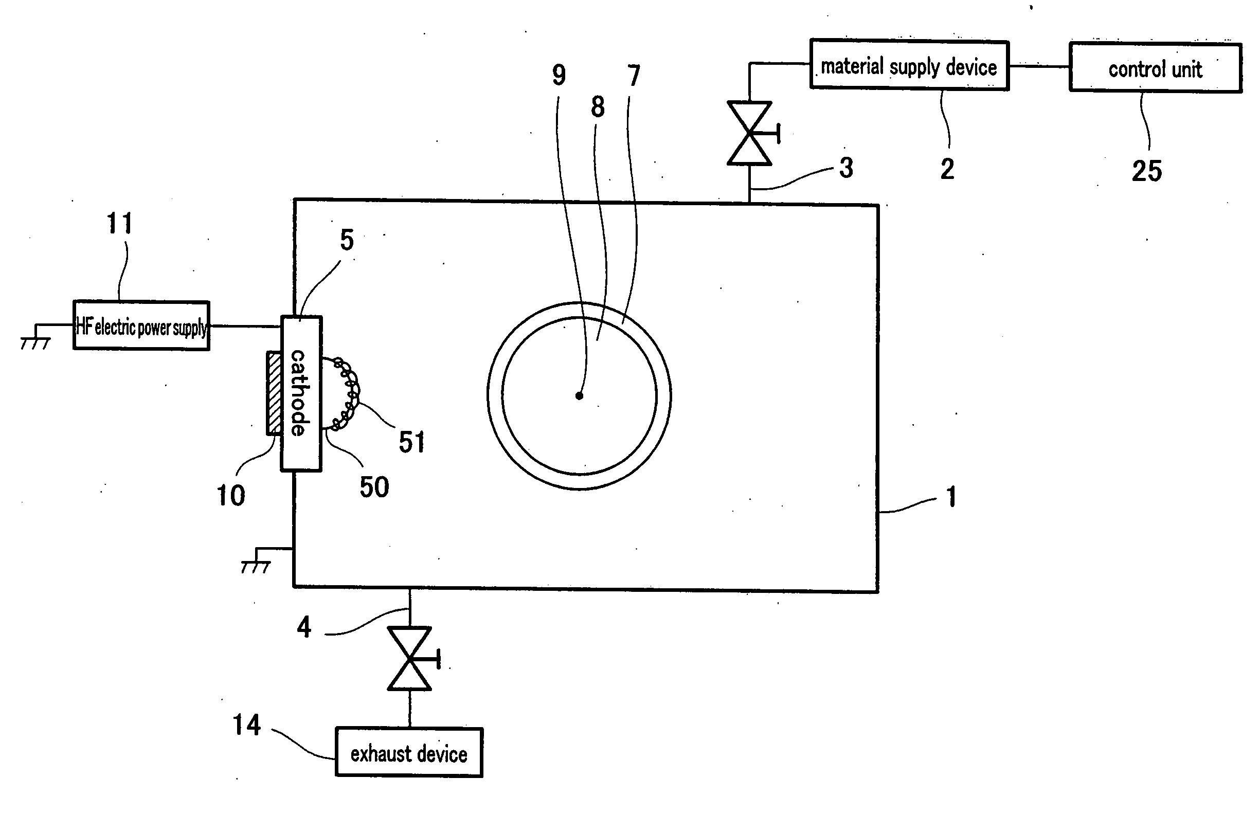
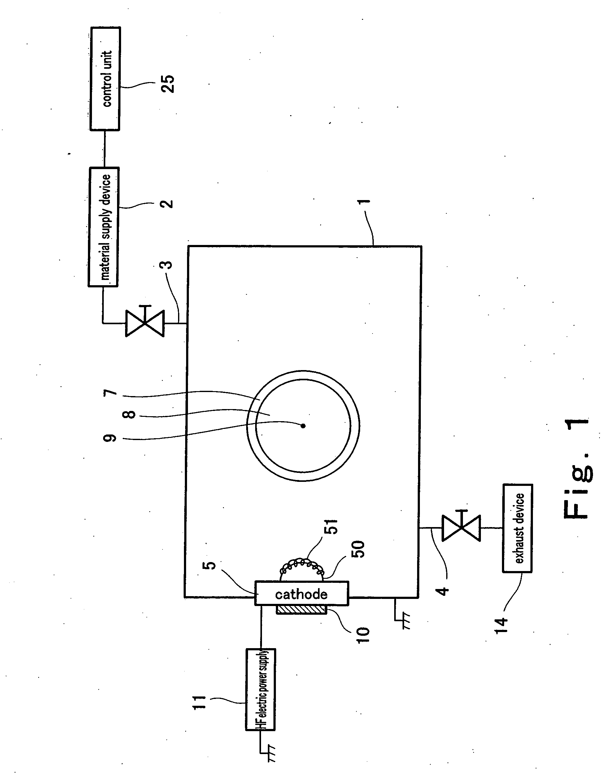
[0037]FIG. 1 is a diagram schematically illustrating a configuration of a film formation system according to embodiment 1 of the present invention. The film formation system shown in FIG. 1 has: a vacuum chamber 1 formed by an electrically conductive member; a material supply device 2 and a supply passageway 3 which supply raw material for film formation and plasma source gas to the vacuum chamber 1; a control unit 25 which controls the material supply device 2; an exhaust device 14 and an exhaust passageway 4 which evacuate the air in the chamber; a cathode 5; a permanent magnet 10 disposed on the rear surface of the cathode 5 (the surface outside the chamber); and a substrate holder 7. Both the supply passageway 3 and the exhaust passageway 4 communicate with the inside of the chamber. A diffusion pump or the like is used as the exhaust device 14.
[0038] The cathode 5 of embodiment 1 is made of Cu. A portion of the cathode 5 projects outwardly from the chamber and the rest of the ...
embodiment 2
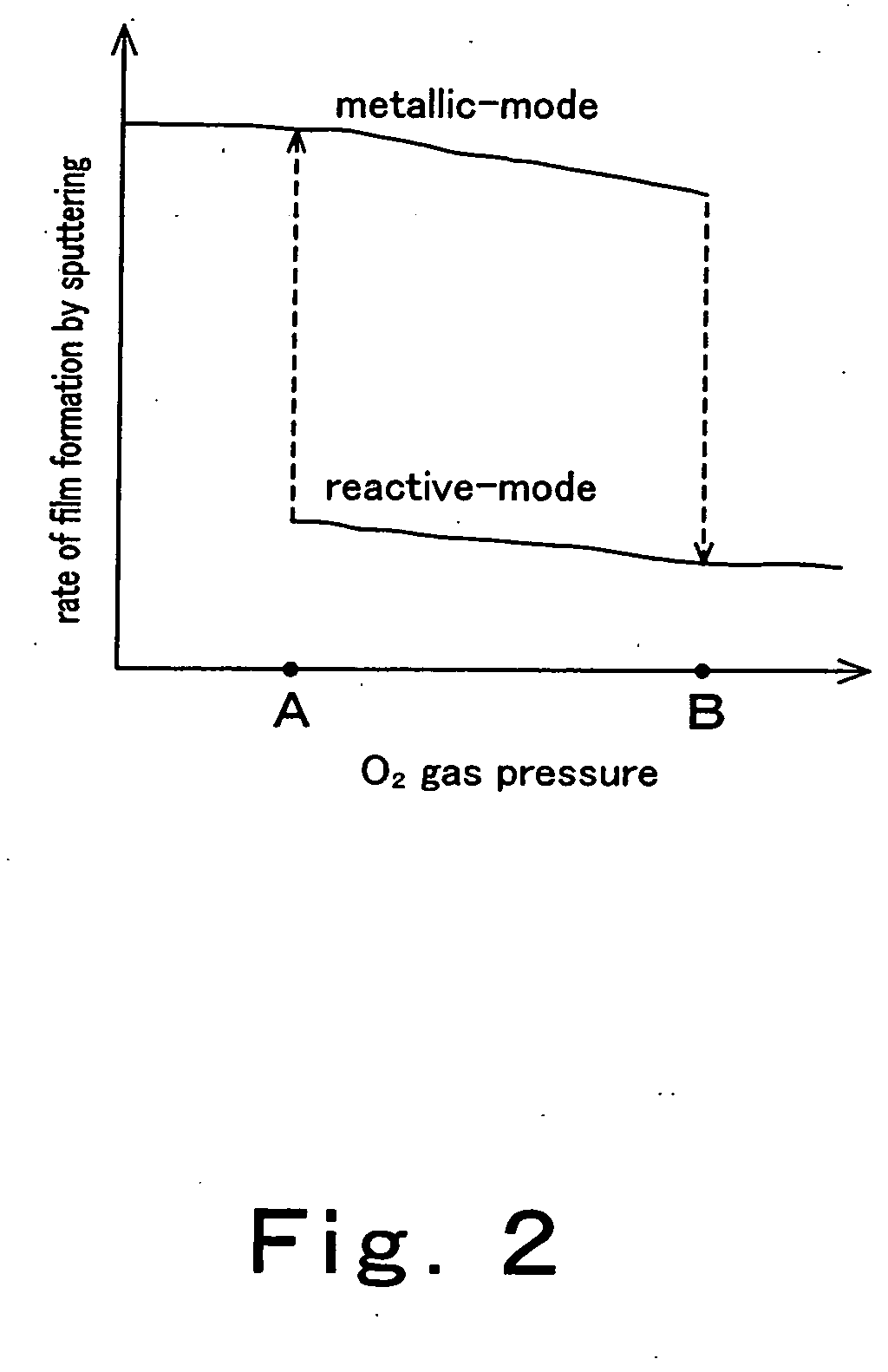
[0051] A film formation system according to a second embodiment of the present invention has the same configuration as that of the film formation system of embodiment 1. Therefore, the present embodiment will be described by making reference to FIG. 1. In the film formation system of the present embodiment, plasma polymerization is carried out in the same way as in the film formation system of embodiment 1. In addition, in the film formation system of the present embodiment, film formation by magnetron sputtering is carried out by generating a metallic-mode plasma in the chamber, as described below.
[0052] To sum up, at the time of film formation by plasma polymerization, the pressure of O2 gas in the chamber is controlled to be higher than or equal to the predetermined pressure level B so that a reactive-mode plasma is generated, as previously described in embodiment 1. By the use of the plasma thus generated, film formation by plasma polymerization is conducted to form a film of H...
embodiment 3
[0056]FIG. 5 is a diagram schematically showing a configuration of a film formation system according to embodiment 3 of the present invention. The film formation system of the present embodiment has the similar structure as that of the film formation system of embodiment 1, but they are different with regard to the point that the film formation system of the present embodiment is provided with a pair of cathodes.
[0057] More specifically, the film formation system of the present embodiment has a pair of cathodes 5A and 5B formed of Cu, wherein a portion of each of the cathodes 5A and 5B is disposed within the chamber and the rest projects outwardly from the chamber. The cathodes 5A and 5B are insulated from the vacuum chamber 1 by an insulating member. The cathodes 5A and 5B are arranged so that their positions are symmetrical relative to the extension line 45 of the diameter of the substrate holder 7 and normal lines of the principal surfaces of the cathodes 5A and 5B run at predet...
PUM
| Property | Measurement | Unit |
|---|---|---|
| Pressure | aaaaa | aaaaa |
| Electric potential / voltage | aaaaa | aaaaa |
| Frequency | aaaaa | aaaaa |
Abstract
Description
Claims
Application Information