
Rugged fabry-perot pressure sensor

Inactive Publication Date: 2007-02-22
SABEUS
View PDF6 Cites 70 Cited by
  • Summary
  • Abstract
  • Description
  • Claims
  • Application Information

AI Technical Summary

Benefits of technology

[0021] In one alternative aspect, the distal end of the optical fiber is polished flat. In another alternative aspect, the distal end of the optical fiber is a curved surface. In yet another alternative aspect, the distal end of the optical fiber is cleaved flat. In yet another alternative aspect, the distal end of the optical fiber has a coating to increase the reflectivity of the distal end of the optical fiber above the reflectivity of a glass to air interface.

Problems solved by technology

Although the reliability of such a quartz crystal is extremely high, the electronics required to measure frequency change are subject to failure particularly when the transducer and its associated electronics are subjected to elevated temperatures, such as temperatures above 125° C.
However, such techniques are either complex, costly, or do not constrain the optical fiber from buckling in the grating region.
However, such a sensor does not constrain the optical fiber against buckling in the region of the grating.
However, such a technique may be difficult and expensive to implement.
Another limitation of the use of fiber Bragg gratings as integral parts of a pressure sensor is that the tension on the optical fiber of such a sensor cannot be very great without breaking the fiber.
Accordingly, such a sensor may have a limited range of sensitivity.
One disadvantage of this construction is that the diaphragm, when it deflects, does not remain perfectly flat as the pressure changes, since at least the periphery of the diaphragm is typically attached to the sensor housing to hold the diaphragm.
This provides multiple reflective paths that distort the spectrum of the light within the Fabry-Perot optical cavity, resulting in measurement errors.
Attempts to improve the sensitivity of such devices by bonding the fiber only partially along its length, leaving a portion of the fiber adjacent to the gap free, results in erroneous measurements due to the unbonded portion of the optical fiber sticking or slipping in the ferrule as the pressure changes.
Moreover, the unbonded sections may move excessively in response to vibrations, resulting in increased measurement error.

Method used


Image

  • Rugged fabry-perot pressure sensor
  • Rugged fabry-perot pressure sensor
  • Rugged fabry-perot pressure sensor

Examples


Embodiment Construction

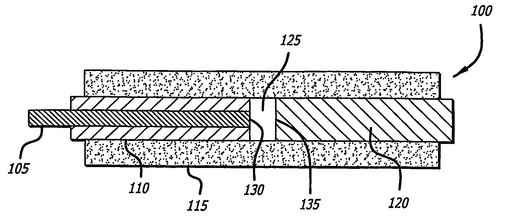
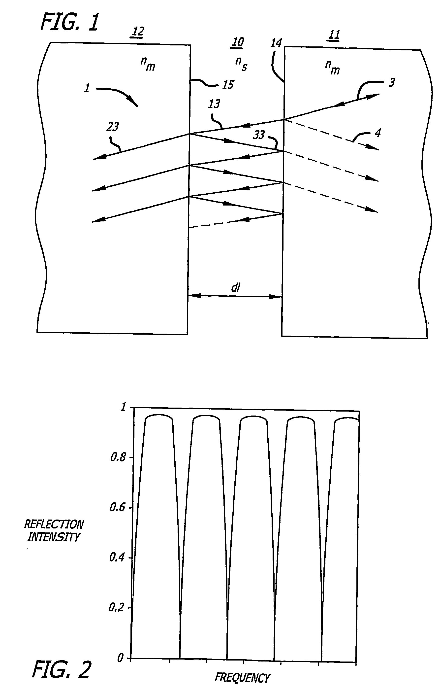
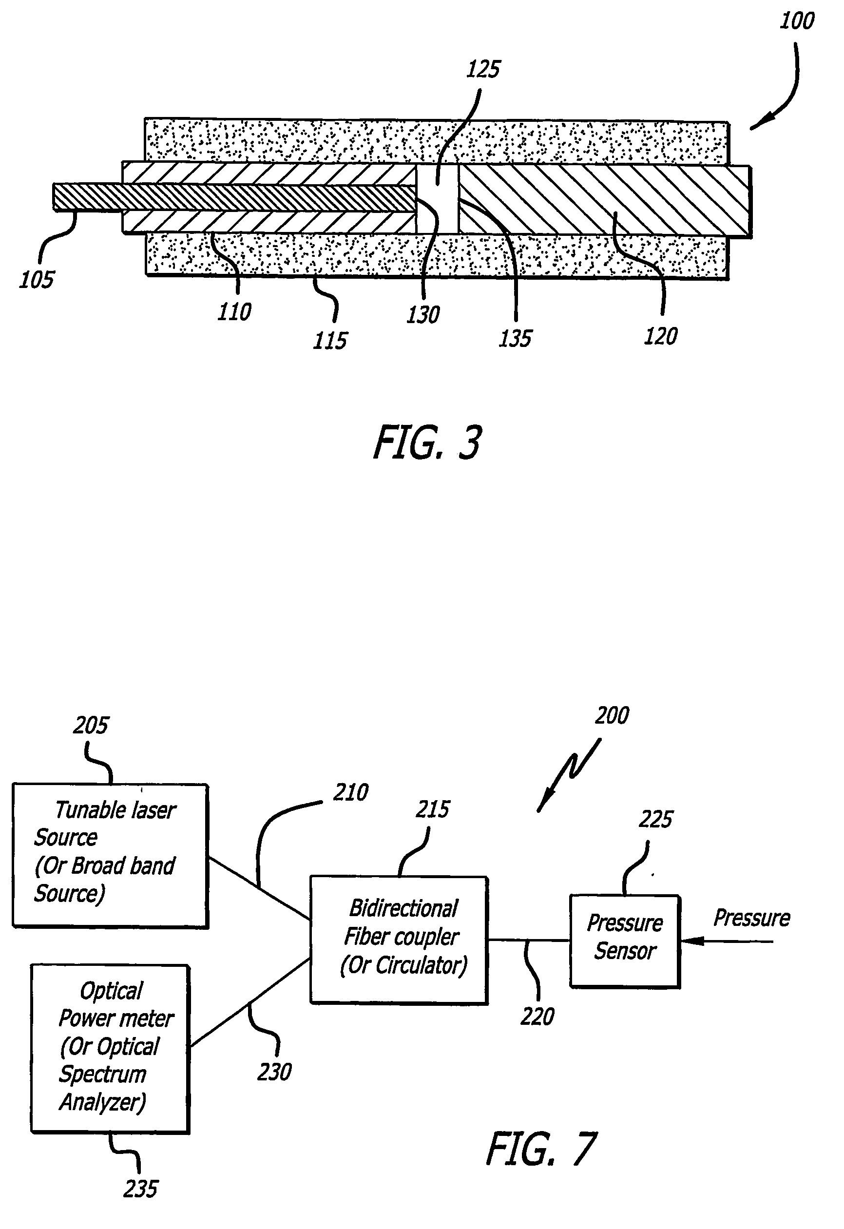
[0037] The present invention as illustrated by way of example in the accompanying drawings, and generally comprises a pressure sensor disposed at the end of a fiber optic that is configured to be deployed down the bore of a well to measure changes in pressure within the well bore. In general, the pressure sensor of the present invention includes a Fabry-Perot optical cavity mounted at the end of the optical fiber. As will be discussed in more detail below, light is transmitted down the optical fiber until it reaches the Fabry-Perot optical cavity. At the Fabry-Perot optical cavity, a portion of the light is reflected, forming an interference within the optical cavity. As pressure changes are transmitted to the optical cavity, the interference within the optical cavity changes. These changes can be detected from the light that is reflected by the optical cavity back up the optical fiber. Using suitable electronics and optical components to analyze and convert the changes in the retur...


PUM


Abstract

A pressure sensor (100) and system for measuring pressure changes, especially in harsh environments, is described. The pressure sensor has a Fabry-Perot optical cavity formed within a tube (115) with a partial reflective mirror (130) provided by an end of an optical fiber (105) and a reflective mirror (135) provided by an end of a plug (120), with a gap (125) formed between. The pressure sensor may be disposed within a sensing chamber of a housing having an opening into the environment to be monitored. Alternatively, an isolator means may be used to isolate the sensor from the environment while communicating pressure changes to the sensing chamber. In another embodiment, the sensing chamber is filled with a compressible non-flowing material.

Description

CROSS-REFERENCES TO RELATED APPLICATIONS [0001] This application claims the benefit of priority to U.S. Provisional Application No. 60 / 508,455, filed Oct. 3, 2003, the subject matter of which is being incorporated herein in its entirety.BACKGROUND OF THE INVENTION [0002] 1. Field of the Invention [0003] The present invention is directed to pressure sensors that are sufficiently robust to be used in harsh environments, such as an oil or gas well. More specifically, the invention is directed to a rugged pressure sensor that incorporates a Fabry-Perot optical cavity with an optical fiber to provide a pressure sensor capable of sensing pressure and pressure changes by analyzing the light reflected by the Fabry-Perot cavity. [0004] 2. Description of Related Art [0005] There are many processes and environments in which it is desirable to know the ambient pressure. One such common process or environment is during exploration and production of hydrocarbons such as oil in which it is necessa...

Claims


Application Information

Patent Timeline
IPC IPC(8): G01B9/02G01B11/02G01LG01L9/00
CPCG01D5/266G01L11/02G01L9/0079G01L9/0007
Inventor SCHMIDT, SIEGMAR
Owner SABEUS
Features
  • Generate Ideas
  • Intellectual Property
  • Life Sciences
  • Materials
  • Tech Scout
  • Unparalleled Data Quality
  • Higher Quality Content
  • 60% Fewer Hallucinations
Learn More