Variable displacement reciprocating pump

a reciprocating pump and variable displacement technology, applied in the direction of positive displacement liquid engines, piston pumps, machines/engines, etc., can solve the problems of fixed ratio gear box that cannot be used to control the pump speed, limited horsepower by the prime mover, and the lowest flow rate output of the pump is limited to the transmission gear ratio

Active Publication Date: 2007-02-22
SERVA CORP
View PDF27 Cites 56 Cited by
  • Summary
  • Abstract
  • Description
  • Claims
  • Application Information

AI Technical Summary

Benefits of technology

[0043] In a different arrangement using the present invention, two pumps can be driven with the same engine without a transmission while one or the other or both of the pumps can be stroked independently per the needs of the job. With a splitter gear box, the power from a single engine can be split and supplied to two separate pumps via secondary input drive shaft...

Problems solved by technology

Thus a fixed ratio gear box that cannot be used to control the pump speed is not considered a transmission for purposes of this application.
The horsepower is limited by the prime mover and the pump design.
In addition, the pump's lowest flow rate output is limited to the transmission gear ratio.
Large volume pumps cannot reach the required low pump rates due to transmission ratio limits.
Smaller pump and transmission arrangements that can reach the required low rates cannot meet the higher rates also required during well service work.
The first disadvantage concerns cost.
Providing the pumps with transmissions and providing multiple pumps, engines and transmissions to achieve the required range of operating conditions is expensive, weighs more and takes up more space.
The second disadvantage of current multi-plunger well service pumps concerns performance.
Pumps using current technology yield a discontinuous, stair step pressure-volume curve, have a limited working range, and are unable to be controlled by a computer.
This method of adjusting the stroke of the plunger employed by Bradley is crude, is inaccurate, is limited in the speed at which it can be accomplished, an...

Method used


Image

  • Variable displacement reciprocating pump
  • Variable displacement reciprocating pump
  • Variable displacement reciprocating pump

Examples


Embodiment Construction

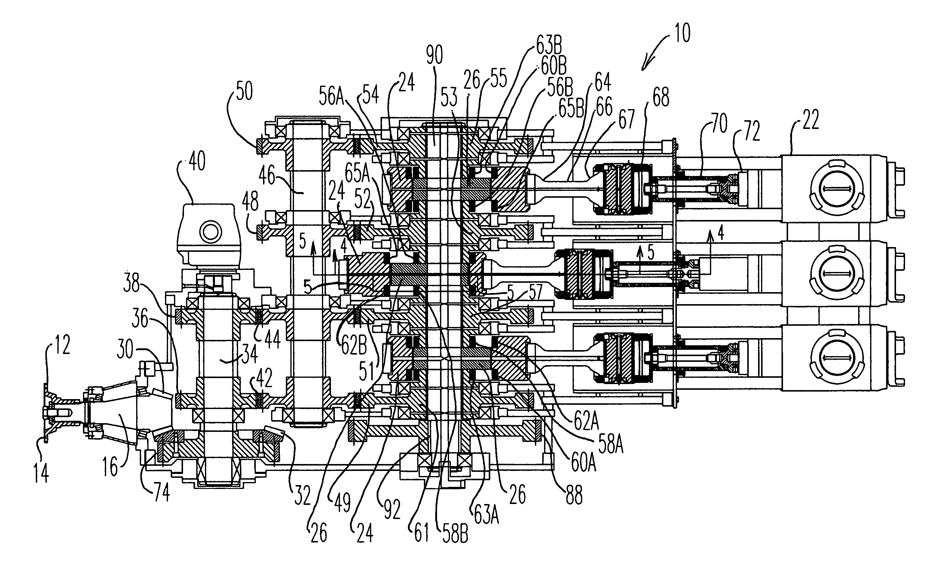
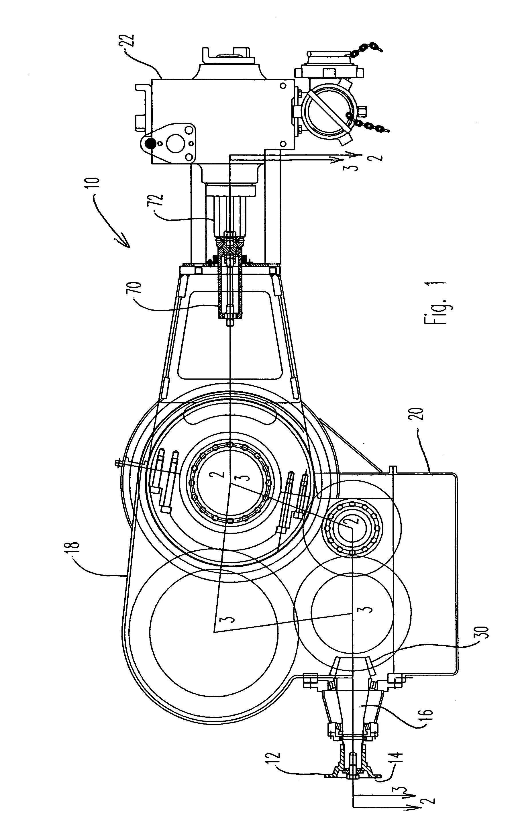
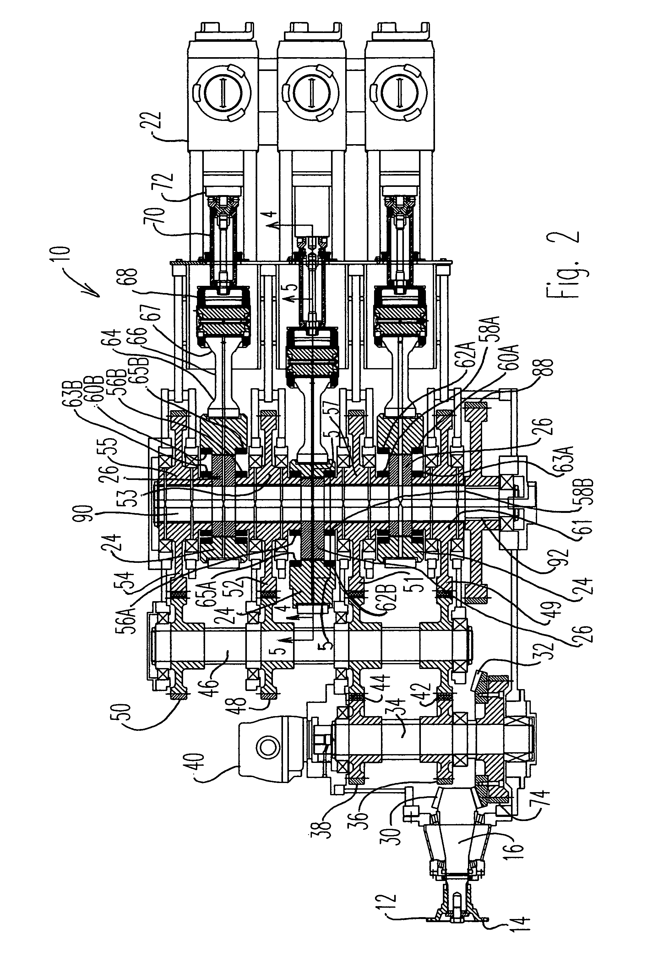
[0056] Referring now to the drawings and initially to FIGS. 1 and 8, there is illustrated a variable displacement reciprocating multi-plunger well service pump 10 constructed in accordance with a preferred embodiment of the present invention. As shown in FIG. 8, the pump 10 is attached on its power end input 12 to a power source or prime mover 11, such as an engine or electric motor. Typically, the prime mover 11 is a diesel engine and the output of the diesel engine requires a power take off (PTO) with a clutch 128 or a torque converter. The clutch 128 is attached to the input of the pump 10 by rotatable input drive shaft 13 and by input drive flange 14. Input drive flange 14 is attached to and turns input pinion shaft 16. The pump prime mover 11 powers the pump 10.

[0057] As shown in FIG. 1, the pump 10 is provided with an external power end case 18, a power end oil reservoir 20, and a pump fluid end 22 where the pumping of fluid actually takes place. As will be more fully describ...


PUM


Abstract

A variable displacement reciprocating pump with pumping rate that is adjustable from zero to maximum stroke while the pump is running. Stroke is varied by changing relative position of pairs of eccentric inner and outer cams that drive the pump's plungers. The pump's input drive shaft drives two gear trains: a first gear train that turns the inner cams and a second gear train that turns the outer cams. These cams normally revolve together with no relative motion occurring between them. A rotary actuator is positioned in the first gear train to rotate the inner cams relative to the outer cams and thereby changes the pump's stroke. A computerized system of sensors and control valves allows the pump to be automatically controlled or limited to any one or combination of desired output flow, pressure and horsepower.

Description

BACKGROUND OF THE INVENTION [0001] 1. Field of the Invention [0002] The present invention relates to a variable displacement reciprocating pump. The invention is described as a multi-plunger well service pump, but is not so limited since the invention can be used for a variety of applications and in a variety of arrangements, including single plunger pumps. [0003] 2. Description of the Related Art [0004] Reciprocating pumps are widely used in a variety of applications. One application involves multi-plunger pumps for oil well service work. These pumps typically are high pressure pumps operating at pressures that range from low pressures to pressures as high as 15,000 psi. The pumping rate varies from low rates to more than 18 barrels per minute. [0005] The pump prime mover, engine or electric motor, that powers the pump is normally coupled to the pump through a transmission. For purposes of this application, transmission will mean any device used between the prime mover and the pump...

Claims


Application Information

Patent Timeline
IPC IPC(8): F04B1/04
CPCF04B9/02F04B49/126Y10T74/2162Y10T74/2107Y10T74/2101Y10T74/2142F04B1/07
Inventor ALLEN, THOMAS E.
Owner SERVA CORP
Why Eureka
Try Eureka