Synthesis gas and carbon dioxide generation method

a technology of synthesis gas and carbon dioxide, which is applied in the direction of hydrogen production, carbon capture, oxygen/ozone/oxide/hydroxide, etc., can solve the problem of limited degree to which steam methane reforming can occur within steam methane reformers

Inactive Publication Date: 2007-02-22
PRAXAIR TECH INC
View PDF10 Cites 58 Cited by
  • Summary
  • Abstract
  • Description
  • Claims
  • Application Information

AI Technical Summary

Benefits of technology

[0012] It is to be further noted that since the flue gas stream has been produced by oxyfuel combustion occurring within the oxygen transport membrane combustor, it predominantly contains carbon dioxide and water. As such, the capture of the carbon dioxide product becomes an inexpensive proposition in that the flue gas stream can be cooled after having indirectly transferred heat to the first endothermic steam methane reforming reaction. The water then can be separated from the flue gas stream after having been cooled to allow the carbon dioxide to be further processed and purified or to be sequestered. In this regard, the flue gas stream can be sufficiently cooled to condense the water contained therein. The water can then be separated from the flue gas stream, by introducing the flue gas stream into a vessel, such as a knock-out drum, to collect the water.

Problems solved by technology

While, there may be potential to extend the reliable performance of oxygen transport membranes to 1400° C., such temperature would still be below the order of temperatures required in a steam methane reformer, typically in excess of 1500° C. Hence, the degree to which steam methane reforming can occur within the steam methane reformer is limited when a flue gas generated by an oxygen transport membrane combustor is used to supply the heat.
This limitation is made up by taking up remaining reforming duty in the gas heated reformer.

Method used


Image

  • Synthesis gas and carbon dioxide generation method
  • Synthesis gas and carbon dioxide generation method

Examples


Embodiment Construction

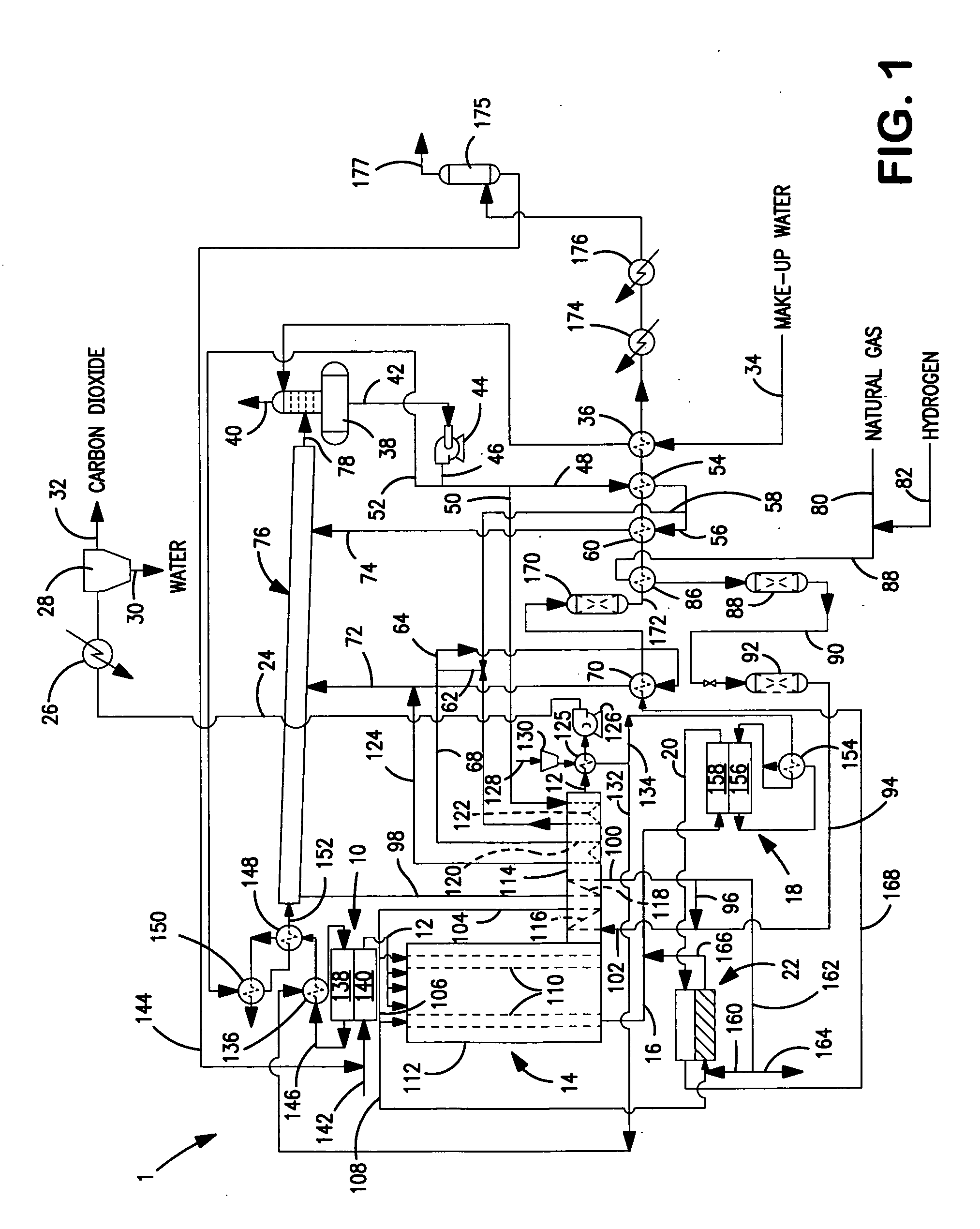
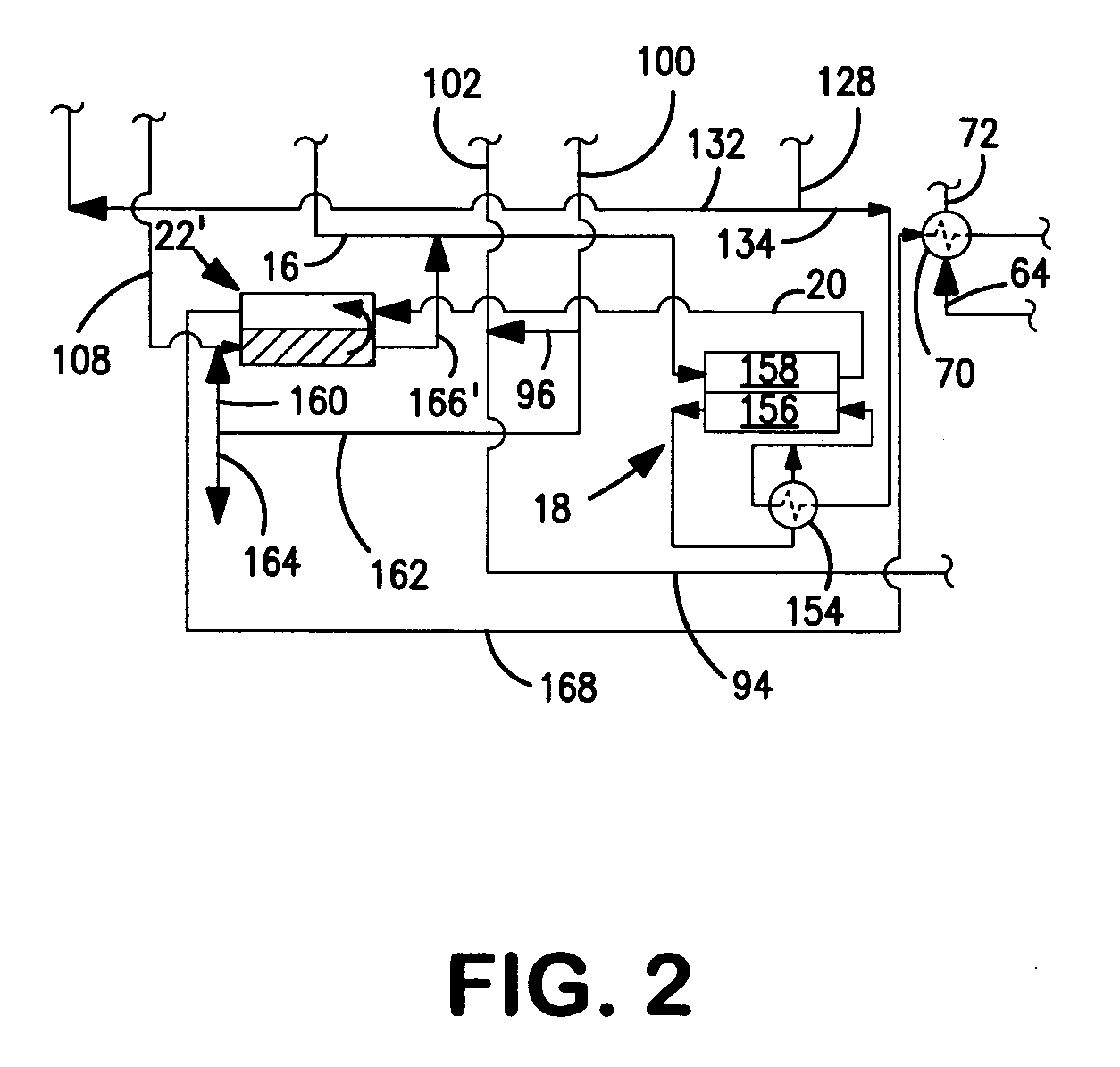
[0019] With reference to FIG. 1, a hydrogen production plant 1 is illustrated for carrying out a method in accordance with the present invention. In this regard, an oxygen transport membrane combustor 10 produces a flue gas stream 12 that is used to supply heat to a primary stage of combined reforming process that is formed by a steam methane reformer 14. FIG. 1 illustrates a case of co-current flue gas and process gas flows. Other arrangements such as countercurrent flow or “side fired” arrangements are possible. Steam methane reformer 14 produces a first synthesis gas stream 16. The flue gas stream 12 upon generation has a temperature of between about 900° C. and about 1200° C. and hence, the oxygen transport membrane employed in oxygen transport membrane combustor 10 can operate at conventional temperatures. The first synthesis gas stream 16 is further reacted in a second stage of the combined reforming process. The second stage is formed by an oxygen transport membrane reactor 1...


PUM

PropertyMeasurementUnit
adiabatic flame temperaturesaaaaaaaaaa
operational temperatureaaaaaaaaaa

Abstract

A method of generating a synthesis gas product stream and carbon dioxide in which a fuel is combusted in an oxygen transport membrane combustor to produce a flue gas stream containing the carbon dioxide and water. Reforming duty is divided between a combined reforming process and a gas heated reformer to produce the product stream. The flue gas stream is used to supply heat to a primary, steam methane reforming stage of the combined reforming process. Residual methane, produced in the primary stage, is reacted in a secondary stage having an oxygen transport membrane reactor. Heat produced in the secondary stage is supplied to the gas heated reactor to support its operation. The flue gas stream is cooled and water is separated therefrom to produce the carbon dioxide at a concentration of at least 85 mol percent.

Description

FIELD OF THE INVENTION [0001] The present invention relates to a method of generating a synthesis gas product stream and carbon dioxide in which hydrocarbons and steam are reacted in a combined reforming process and in a gas heated reformer. More particularly, the present invention relates to such a method in which heat is supplied to a primary steam methane reforming stage of the combined reforming process by a flue gas stream that contains the carbon dioxide and heat is supplied to the gas heated reformer from a secondary catalytic partial oxidation stage of the combined reforming process. Even more particularly, the present invention relates to such a method in which oxygen transport membranes are employed in a combustor to generate the flue gas and in the secondary catalytic partial oxidation stage. BACKGROUND OF THE INVENTION [0002] Synthesis gases are conventionally produced by conducting an endothermic steam methane reforming reaction within a steam methane reformer. A steam ...

Claims


Application Information

Patent Timeline
Patent Type & Authority Applications(United States)
IPC IPC(8): C01B3/24C01B32/50
CPCB01J8/009B01J8/067B01J2219/00006C01B3/382C01B3/384C01B3/386C01B13/0251C01B2203/0233C01B2203/0261C01B2203/0811C01B2203/0822C01B2203/0827C01B2203/0833C01B2203/0894C01B2203/1241C01B2203/1288C01B2203/141C01B2203/142C01B2203/80C01B2203/86C01B2210/0046Y02P20/128Y02P30/30C01B32/50Y02P20/10Y02P30/00
Inventor DRNEVICH, RAYMOND FRANCIS
Owner PRAXAIR TECH INC
Why Eureka
Try Eureka