Fuel electrode of solid polymer electrolyte fuel cell

a fuel cell and solid polymer technology, applied in the direction of active material electrodes, cell components, electrochemical generators, etc., can solve the problem of increasing the potential of the fuel electrode, and achieve the effect of maintaining performance and reducing density

Inactive Publication Date: 2007-02-22
TANAKA PRECIOUS METAL IND +1
View PDF2 Cites 45 Cited by
  • Summary
  • Abstract
  • Description
  • Claims
  • Application Information

AI Technical Summary

Benefits of technology

[0015] This point will now be explained taking as an example a case in which hydrogen is applied as fuel. At the fuel electrode in a condition in which fuel is being supplied, proton is produced by a catalytic oxidation of hydrogen molecules, and this decomposition reaction of hydrogen molecules is normally dominant. The potential of the fuel electrode in this condition is approximately 0 V (with reference to the hydrogen electrode). On the other hand, when the fuel shortage is created, the electrolysis reaction of the water that is contained in the fuel or held by the fuel electrode or a solid polymer electrolyte arises at the fuel electrode in order to supply proton that is lacking, and this reaction becomes dominant. The potential of the electrolysis of water is 1.23 V or above (with reference to the hydrogen electrode). Therefore, the creation of the fuel shortage increases the potential of the fuel electrode.
[0029] The fuel electrode according to the present invention has a multilayered structure consisting of at least two layers. For producing the same, it is preferable to form a reaction layer on the surface of a solid polymer electrolyte membrane, form a water decomposition layer on a diffusion layer and join the reaction layer and the water decomposition layer. In the production of fuel cell electrodes, generally, a mixed paste (catalyst paste) of a catalyst with a resin is produced, and the paste is applied on the surface of either a solid polymer electrolyte membrane or a diffusion layer, dried and hot-pressed to form a solid electrode. In this case, the denseness of the electrode depends on the substrate on which the paste is applied, and a porous electrode may be prepared by applying the paste on a porous substrate and burning. As described above, the water decomposition layer is preferably porous. In consideration of this, it is possible to prepare a porous water decomposition layer utilizing a porous diffusion layer as a substrate for applying paste. Thus, it is possible to achieve a multilayered-structure electrode of a preferred embodiment by forming a porous water decomposition layer at the diffusion layer side and forming a reaction layer at the polymer membrane side, thereby providing a difference in the denseness between the both layers.

Problems solved by technology

Therefore, the creation of the fuel shortage increases the potential of the fuel electrode.

Method used


Image

  • Fuel electrode of solid polymer electrolyte fuel cell
  • Fuel electrode of solid polymer electrolyte fuel cell
  • Fuel electrode of solid polymer electrolyte fuel cell

Examples


first embodiment

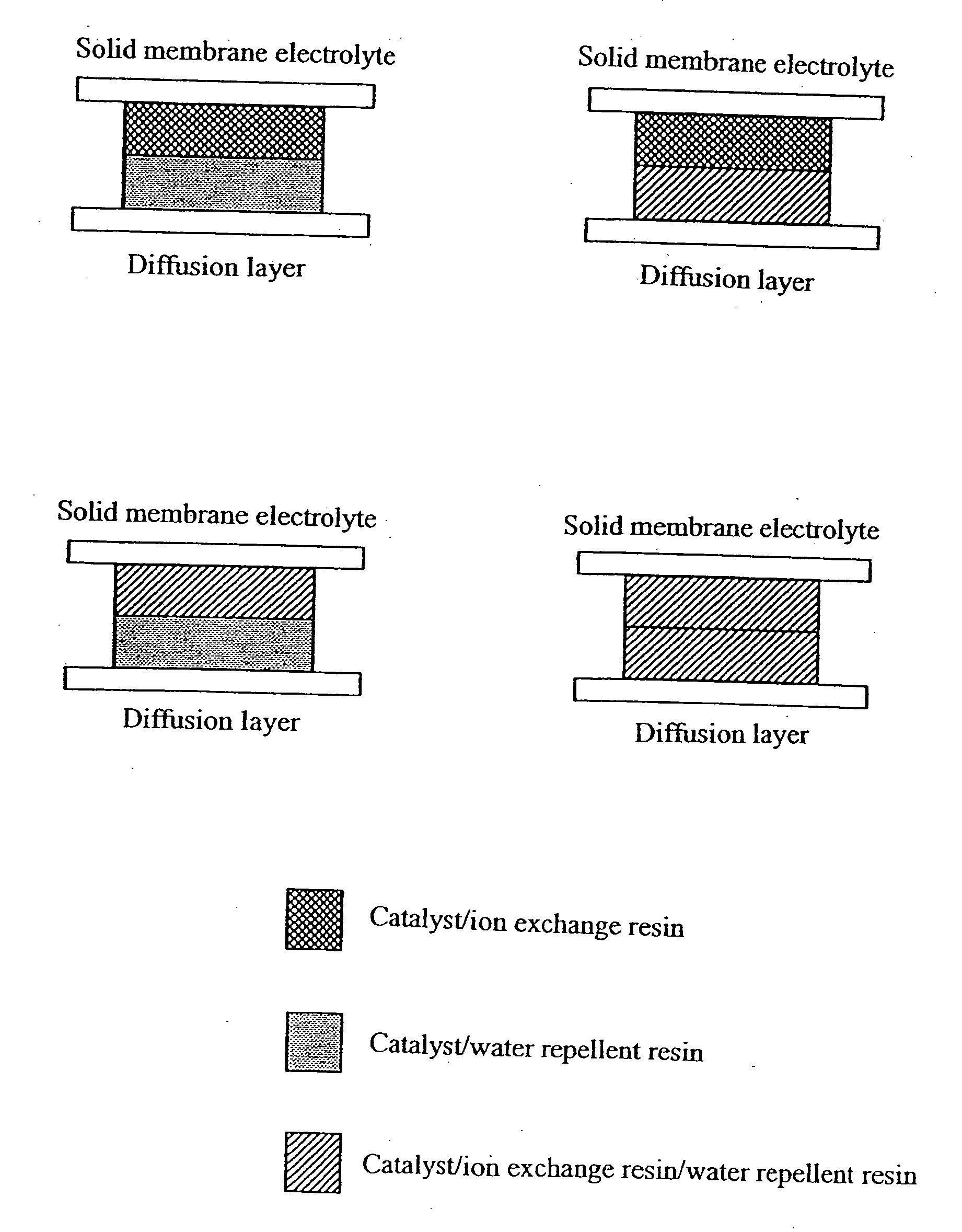
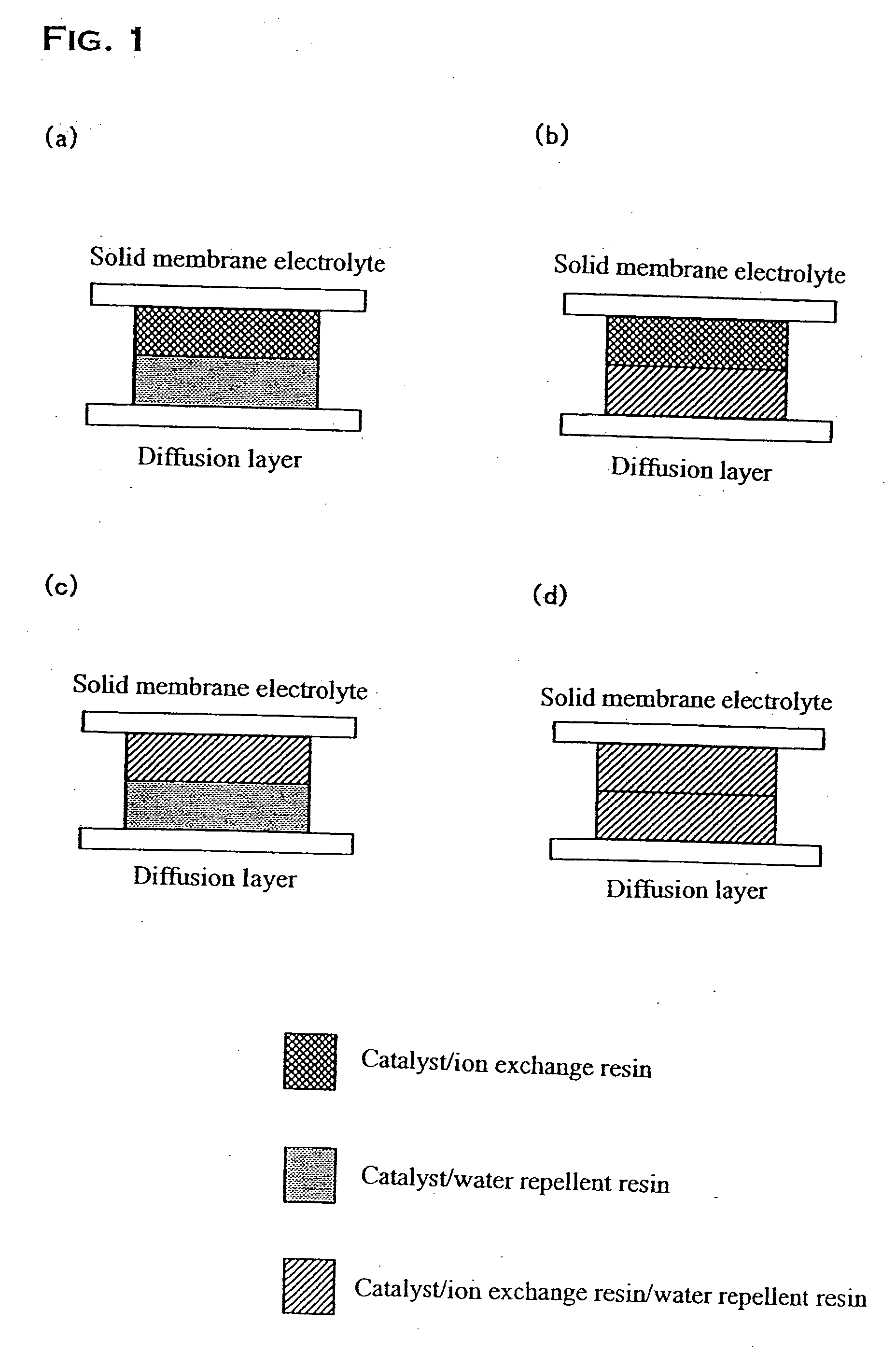
[0038] In the present embodiment, the fuel electrode corresponding to (a) in FIG. 1 was produced. First, 1 g of fine powders of the resin prepared by spray-drying a 5% solution of the above described ion exchange resin and 2 g of the above described platinum-ruthenium catalyst were added to 25 mL of an aqueous solution of 1-propanol, and they were mixed for 50 minutes with a ball mill, preparing a catalyst paste. Next, the catalyst paste was applied by printing on the surface of a polymer electrolyte membrane (Nafion 112) such that the loading of platinum is 0.2 mg / cm2 to form the reaction layer.

[0039] On the other hand for the water decomposition layer, 1 g of the above described fine powders of the water repellent resin and 1.7 g of the above described platinum catalyst were added to 25 mL of an aqueous solution of 1-propanol, and they were mixed for 50 minutes with a ball mill, preparing a catalyst paste. Next, the catalyst paste was applied by printing on the surface of a diffu...

second embodiment

[0041] In the present embodiment, the fuel electrode corresponding to (b) in FIG. 1 was produced. The reaction layer was produced in a manner similar to First Embodiment. On the other hand, an ion exchange resin was further added to the water decomposition layer in the present invention. Specifically, 1 g of fine powders of the ion exchange resin was further added when producing the catalyst paste for the water decomposition layer, other processes being similar to First Embodiment. The produced reaction layer and water decomposition layer were bonded to form the fuel electrode by a method similar to First Embodiment.

third embodiment

[0042] In the present embodiment, the fuel electrode corresponding to (c) in FIG. 1 was produced. A water repellent resin was further added to the reaction layer of this embodiment. Specifically, 1 g of fine powders of the water repellent resin was further added when producing the catalyst paste for the reaction layer, other processes being similar to First Embodiment. On the other hand, the water decomposition layer was produced in a manner similar to First Embodiment. The produced reaction layer and water decomposition layer were bonded to form the fuel electrode by a method similar to First Embodiment.


PUM

PropertyMeasurementUnit
specific surface areaaaaaaaaaaa
flow rateaaaaaaaaaa
current densityaaaaaaaaaa

Abstract

The present invention provides a fuel electrode of a solid polymer electrolyte fuel cell for advancing a fuel cell reaction to oxidize the fuel introduced through a diffusion layer, comprising at least one reaction layer which is in contact with a solid polymer electrolyte membrane and advances the fuel cell reaction and at least one water decomposition layer which is in contact with the diffusion layer and electrolyzes the water in the fuel electrode. The layer taking charge of the fuel cell reaction is protected by providing the fuel electrode having a multilayer structure and providing the layer for preferentially performing the electrolysis of the water contained in the fuel or the like. This results in a fuel electrode in which the reduction of the electrode performance will not easily occur even when fuel shortage may be created.

Description

CROSS-REFERENCE TO RELATED APPLICATIONS [0001] This application is a continuation application of non-provisional U.S. Ser. No. 10 / 464,486, filed Jun. 19, 2003.BACKGROUND OF THE INVENTION [0002] 1. Field of the Invention [0003] The present invention relates to a fuel electrode of a solid polymer electrolyte fuel cell. More particularly, the present invention relates to a fuel electrode of a solid polymer electrolyte fuel cell in which the reduction of the electrode performance is difficult to occur even in low fuel conditions caused by an interruption of fuel supply or the like. [0004] 2. Description of the Related Art [0005] Fuel cells have high expectations for a next-generation power generation system. In particular, a solid polymer electrolyte fuel cell using a solid polymer electrolyte as an electrolyte is promising as a power supply for electric vehicles because it operates at relatively low temperatures compared with other types of fuel cells such as a phosphoric acid fuel cel...

Claims


Application Information

Patent Timeline
Patent Type & Authority Applications(United States)
IPC IPC(8): H01M8/18H01M8/10H01M4/94H01M4/88H01M4/86H01M4/90H01M4/92H01M8/04
CPCH01M4/8605H01M4/861H01M4/8615H01M4/8657H01M4/8807H01M4/881H01M4/8828H01M4/92H01M4/926H01M8/04171H01M8/04238H01M8/1004H01M2004/8684Y02E60/50H01M4/86
Inventor TADA, TOMOYUKIINOUE, MASAHIKO
Owner TANAKA PRECIOUS METAL IND
Why Eureka
Try Eureka