Methods of and apparatus for monitoring heart motions

a non-invasive and heart-moving technology, applied in the field of methods and apparatus for non-invasive monitoring of heart motion, can solve the problems of insufficient coupling between non-invasive mechanical methods and external movement generated by the heart, inaccurate mechanical methods, and low use value, so as to reduce the cost of quality control and provide the display with substantially less noise level

Inactive Publication Date: 2007-02-22
CANFORM MEDICAL
View PDF5 Cites 8 Cited by
  • Summary
  • Abstract
  • Description
  • Claims
  • Application Information

AI Technical Summary

Benefits of technology

[0020] These mechanical and optical motion amplifiers have the advantage that they provide the displays with noise levels substantially less than when electronic amplifications alone are utilized.
[0021] In the preferred embodiment of the invention, the accelerometer is adjustable in position along the load section of the lever in order to correspondingly adjust the magnitude of its motion. This largely eliminates inter-instrument differences, and enables comparison of data results between centres of clinical research as well as greatly reducing the cost of quality control in the manufacturing process.

Problems solved by technology

However, mechanical methods are inaccurate because of physical differences between subjects.
For example, the intensity of heart sounds cannot be accurately measured because of the fat thickness layer differences.
Some non-invasive mechanical methods do not couple properly to the external movement generated by the heart and are therefore of little use.
The electrical techniques cannot correlate to the force of cardiac contraction and are therefore of little use, and imaging techniques are also subject to this problem.
In a normally functioning heart, this relationship may hold true, but this finding is unreliable because the head pressure of the cardiovascular system is unknown.
None of the above-mentioned prior methods or techniques can accurately measure the isovolumic phase of the heart cycle, which is the most important parameter to measure in identifying coronary artery disease.
While this prior patent disclosed a restraining system to hold the sensing mechanism in position, it was found that the apparatus is extremely sensitive to gravity because the force resulting from the weight of the sensing mechanism and a sensor restraining system varied in dependence on the vertical and horizontal position of the subject under test.
Consequently, a large cardiac force would decouple the sensing mechanism, so that a subsequent low magnitude force would be recorded poorly or not at all.
These weak forces were so poorly recorded that very large electronic amplification was used, resulting in a poor signal-to-noise ratio and the recording of mostly noise.
The poor coupling resulted in false data, which showed a poor correlation between the isovolumic contraction phase and the ejection phase of the heart cycle in nominal hearts, as shown by a clinical study.
Another result was that the diastolic part of the cycle could not be recorded.
Furthermore, this prior apparatus was difficult to operate because positioning the sensor on the thyroid cartilage was difficult as elastic members forming parts of the restraining system had to be in tension balance to prevent the sensing mechanism from being moved to one side or another of the thyroid cartilage, causing erroneous data.
Also, with this prior apparatus, mechanical interference caused by the sensor restraining system and an accelerometer forming part of the sensing mechanism contacted clothing, pillows, beards, fatty neck tissue, and in the case of a short neck contacted the chest, resulting in huge errors.
Because no coupling apparatus was provided in this prior system, the addition of more sensors was not possible nor could reliable data be obtained.
Also, this prior system employed wire connections extending directly to a recorder, resulting in stiffness and inertial effects due to interference of the wiring with the motion of the sensor.

Method used


Image

  • Methods of and apparatus for monitoring heart motions
  • Methods of and apparatus for monitoring heart motions
  • Methods of and apparatus for monitoring heart motions

Examples


Embodiment Construction

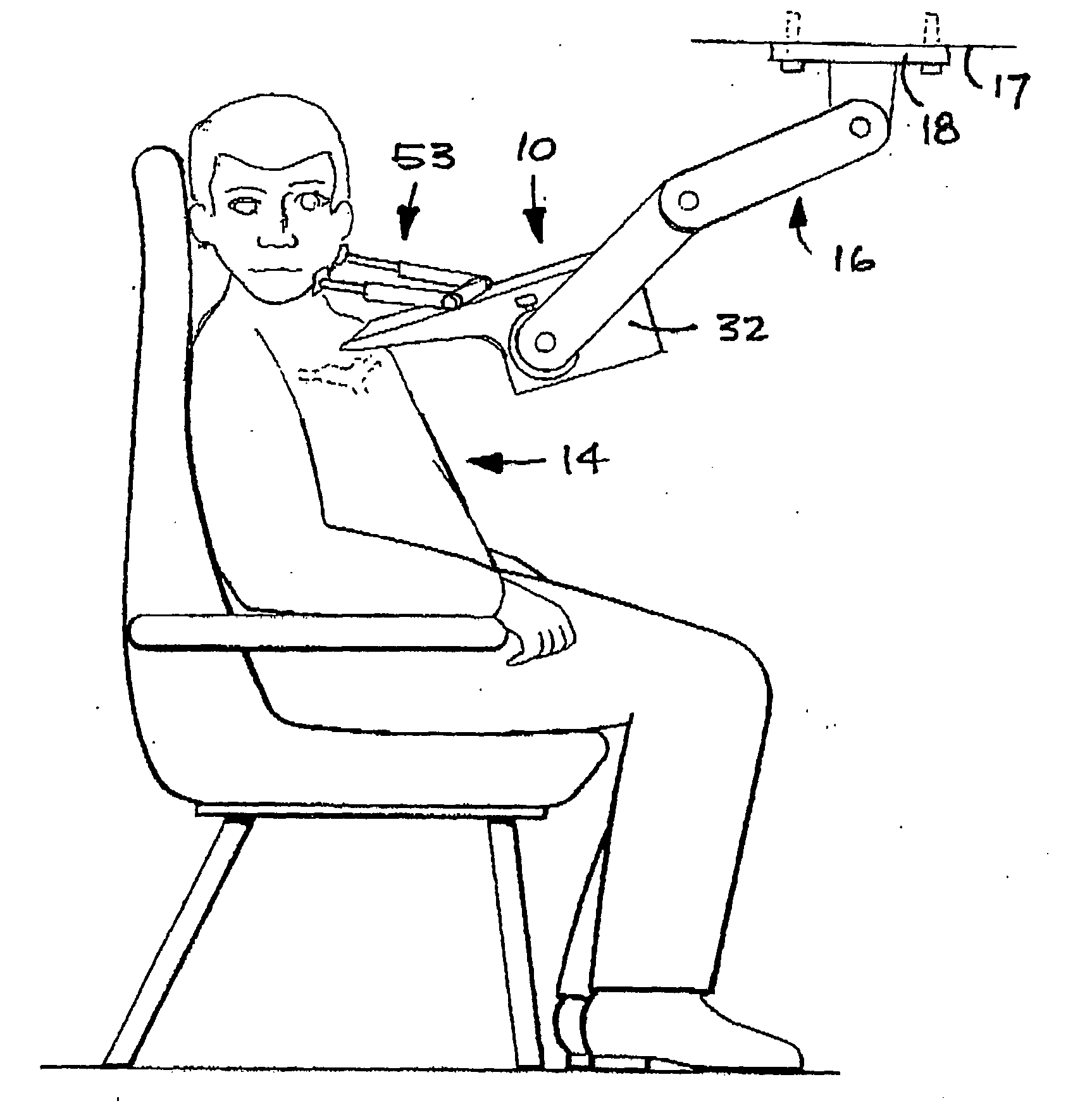
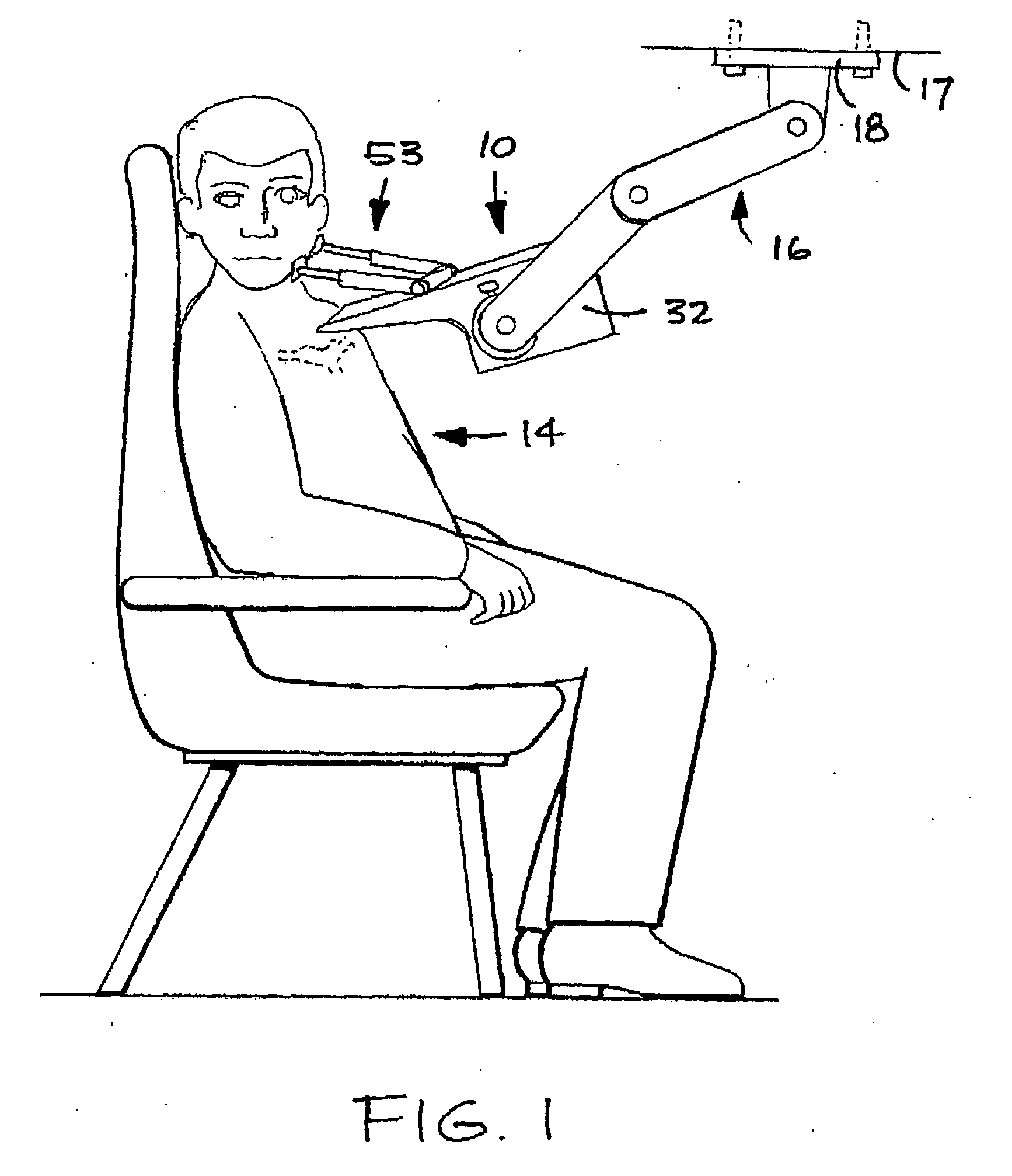
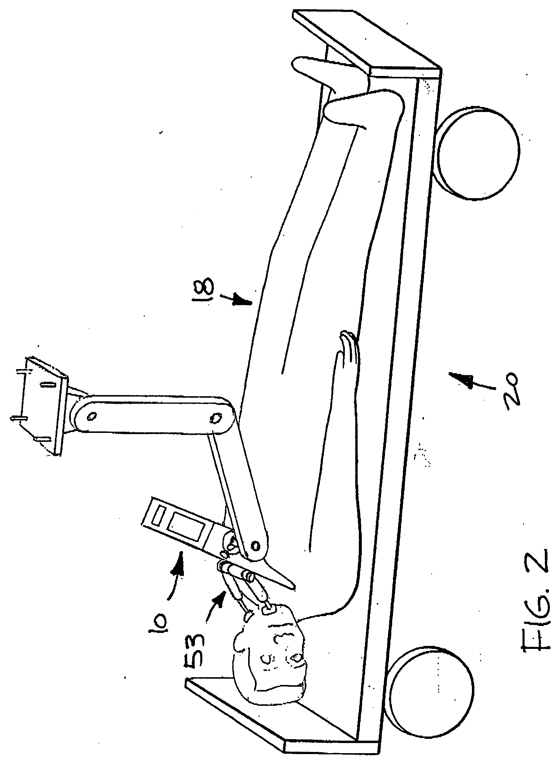
[0044] To facilitate understanding of the various modes of operation of the apparatus of FIG. 1, which is a sensor apparatus indicated generally by reference numeral 10 in FIG. 1, the sensor apparatus 10 is shown in coupled relationship to subjects in different positions in FIGS. 1 to 4 of the accompanying drawings. Accordingly, FIGS. 1 to 4 will firstly be described below, before a more detailed description of the construction and operation of the sensor apparatus 10.

[0045] Measurement of the heart's motion, such as its acceleration, is important as the motion of the heart is a function of force which arises from a change in momentum of the heart mass and the ejection of blood during the various phases of the heart cycle. When a heart abnormality appears, the pattern and the amplitude of these forces change, thereby yielding diagnostic value.

[0046] The heart generates both strong and weak forces, which are all of importance in diagnosis. The method and apparatus described below e...


PUM


Abstract

A method of and an apparatus for monitoring the heart motion of a subject employ a probe which can be coupled to the aortic arch or to the thyroid cartilage of the subject for detecting movements caused by the heart motion and displaying the accelerations and displacement of the heart motion on an acceleration display and a displacement display. A mechanical motion amplifier amplifies the acceleration and an optical amplifier amplifies the displacement to counteract noise.

Description

BACKGROUND OF THE INVENTION [0001] 1. Field of the Invention [0002] The present invention relates to methods of and apparatus for non-invasively monitoring heart motion and is useful for the non-invasive monitoring of cardiac functions, in particular, but not exclusively, of human hearts. [0003] 2. Description of the Related Art [0004] In the past, methods for the non-invasive monitoring of cardiac function have included:—[0005] Mechanical methods, for example, pulse recording of the jugular carotid artery or apex cardiography. [0006] Electrical techniques, for example, electrocardiograms (ECGs). [0007] Imaging techniques, including echocardiology, radiography and magnetic resonance imaging (MRI). [0008] However, mechanical methods are inaccurate because of physical differences between subjects. For example, the intensity of heart sounds cannot be accurately measured because of the fat thickness layer differences. [0009] Some non-invasive mechanical methods do not couple properly to...

Claims


Application Information

Patent Timeline
Patent Type & Authority Applications(United States)
IPC IPC(8): A61B5/02
CPCA61B5/0205A61B5/0404A61B5/08A61B5/1114A61B5/1126A61B5/6822A61B5/6831A61B7/04A61B2562/0219A61B5/6835A61B5/332
Inventor KOBLANSKI, JOHN
Owner CANFORM MEDICAL
Why Eureka
Try Eureka