Systems and methods for cooling electronics components employing vapor compression refrigeration with selected portions of expansion structures coated with polytetrafluorethylene

Inactive Publication Date: 2007-03-01
IBM CORP
View PDF35 Cites 55 Cited by
  • Summary
  • Abstract
  • Description
  • Claims
  • Application Information

AI Technical Summary

Benefits of technology

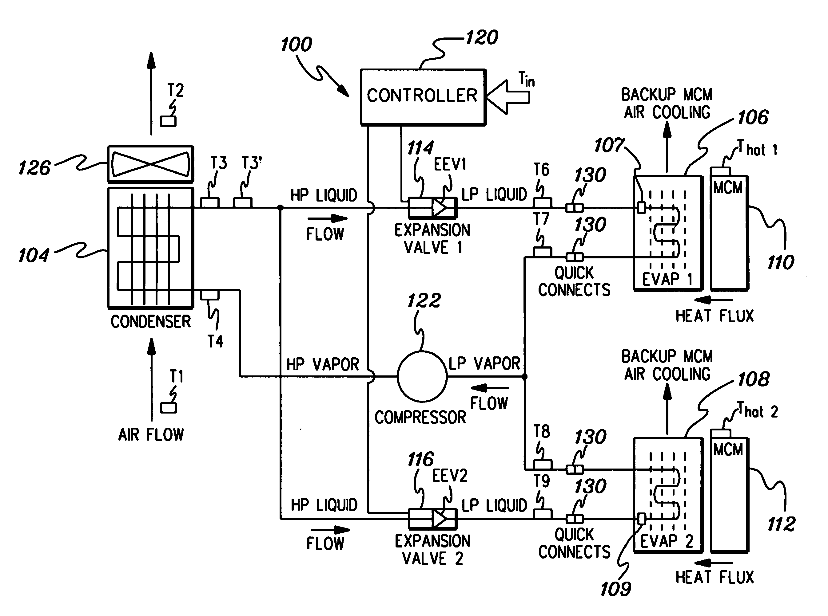
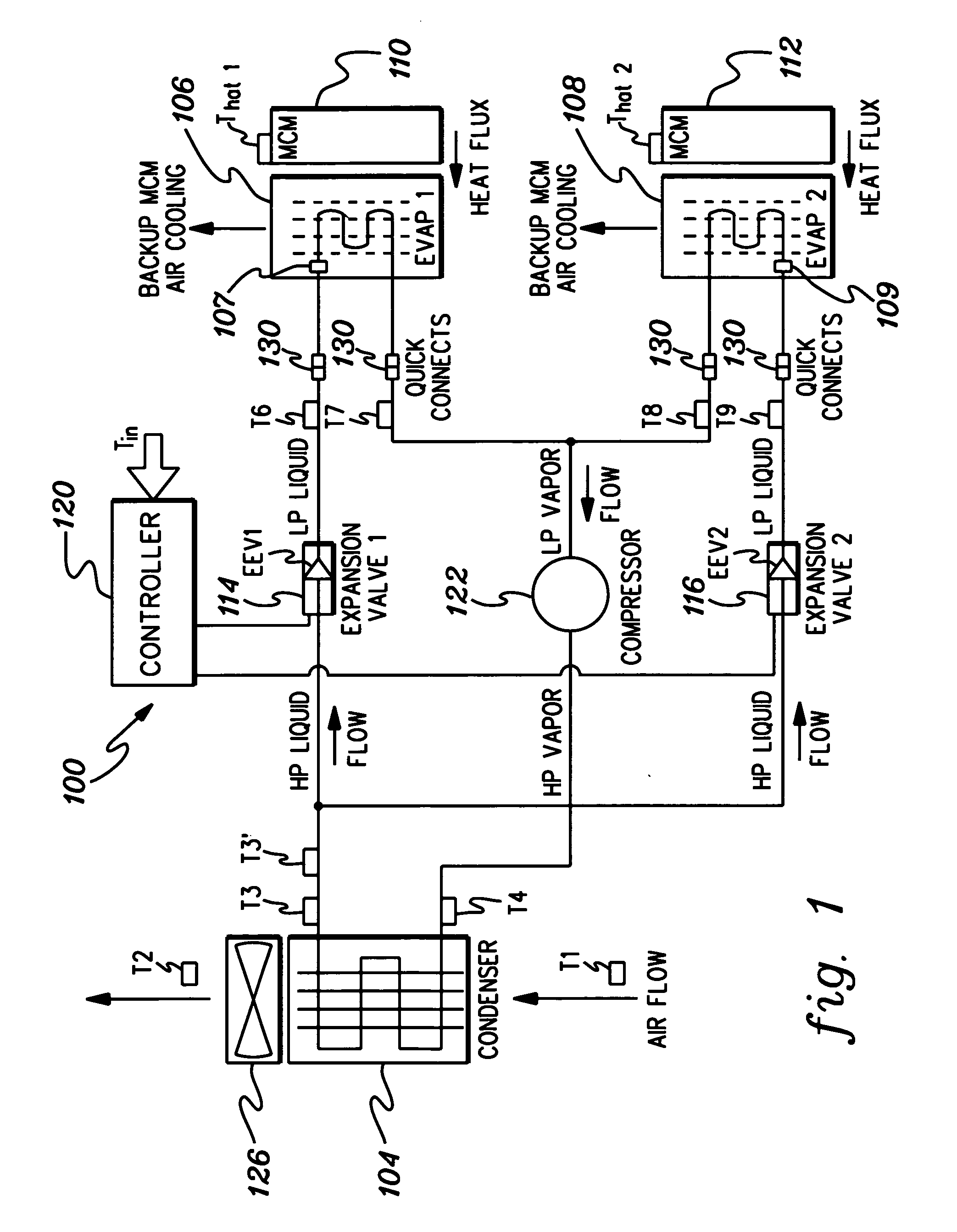
[0005] In vapor compression refrigeration systems employed for cooling one or more heat generating electronics components, it has been discovered that material can agglomerate in certain pressure drop areas of expansion structures within the vapor compression refrigeration system. During refrigerant/oil transport through a hot compressor, any long-chain molecules and other typically non-soluble compounds at room temperature can go into solution in the hot mixture. These, as well as other physically transported impurities, then fall out of solution when the refrigerant/oil cools down. A layer of “waxy” material can build up in the pressure drop areas and act as a sticky substance which then catches other impurities. This material has been found to amass on expansion structures such as expansion valves, and particularly on the pin and orifice control region in the refrigerant flow path of the expansion valve. This amassing of material can interfere with the no

Problems solved by technology

This amassing of material can interfere with the normal control volumes and interfere with the control of motor steps (due to unpredictable valve characteristic changes).
This is particularly true when the vapor compression refrigeration system is employed in a cooling application for removing heat from a heat

Method used


Image

  • Systems and methods for cooling electronics components employing vapor compression refrigeration with selected portions of expansion structures coated with polytetrafluorethylene
  • Systems and methods for cooling electronics components employing vapor compression refrigeration with selected portions of expansion structures coated with polytetrafluorethylene
  • Systems and methods for cooling electronics components employing vapor compression refrigeration with selected portions of expansion structures coated with polytetrafluorethylene

Examples


Example

[0019] As used herein, the term “electronics rack” includes any frame, rack, blade server system, etc., having at least one heat generating electronics component of a computer system or electronics system, and may be, for example, a stand alone computer processor having high, mid or low end processing capability. In one embodiment, an electronics rack may comprise multiple books, each book having one or more heat generating electronics components requiring cooling. Each “heat generating electronics component” may comprise an electronic device, an electronics module, an integrated circuit chip, a multi-chip module, etc. An “expansion structure” is any structure or area in a vapor compression refrigeration system where there is a pressure drop, and thus refrigerant expansion during a refrigerant compression / expansion cycle. As used herein, the term “expansion structure” includes any structure of a pressure drop area and adjacent areas where an agglomeration would effect an expansion s...


PUM


Abstract

Systems and Methods of cooling heat generating electronics components are provided employing vapor compression refrigeration. In one embodiment, the vapor compression refrigeration system includes a condenser, at least one expansion structure, at least one evaporator, and a compressor coupled in fluid communication to define a refrigerant flow path, and allow the flow of refrigerant therethrough. The at least one evaporator is coupled to the at least one heat generating electronics component to facilitate removal of heat produced by the electronics component. At least a portion of the at least one expansion structure is coated with a polytetrafluorethylene in the refrigerant flow path for inhibiting accumulation of material thereon. The polytetrafluorethylene coating has a thickness sufficient to inhibit accumulation of material in a pressure drop area of the expansion structure without significantly changing a pressure drop characteristic of the pressure drop area.

Description

TECHNICAL FIELD [0001] The present invention relates generally to heat transfer mechanisms, and more particularly, to cooling systems and methods for removing heat generated by one or more heat generating electronics components. More particularly, the present invention relates to cooling systems and methods employing vapor compression refrigeration. BACKGROUND OF THE INVENTION [0002] As is known, operating electronic devices produce heat. This heat should be removed from the devices in order to maintain device junction temperatures within desirable limits. Failure to remove produced heat results in increased device temperatures, potentially leading to thermal runaway conditions. Several trends in the electronics industry have combined to increase the importance of thermal management, including heat removal for electronics devices, particularly in technologies where thermal management has traditionally been less of a concern, such as CMOS. In particular, the need for faster and more ...

Claims


Application Information

Patent Timeline
IPC IPC(8): F25B41/06F25D23/12
CPCF25B5/02F25B41/062F25B2341/0653F25B2500/04Y02B30/72Y02B30/70F25B41/35
Inventor KEARNEY, DANIEL J.MARNELL, MARK A.PORTER, DONALD W.
Owner IBM CORP
Why Eureka
Try Eureka