
Miniature linear motor driving device and auto-focus lens device using the same

Inactive Publication Date: 2007-03-01
POWERGATE OPTICAL INC
View PDF3 Cites 33 Cited by
  • Summary
  • Abstract
  • Description
  • Claims
  • Application Information

AI Technical Summary

Benefits of technology

[0009] The primary object of the present invention is to provide a miniature linear motor driving device and auto-focus lens using the same, which offers the advantages of smaller size, simpler structure and less power consumption as compared to prior art.
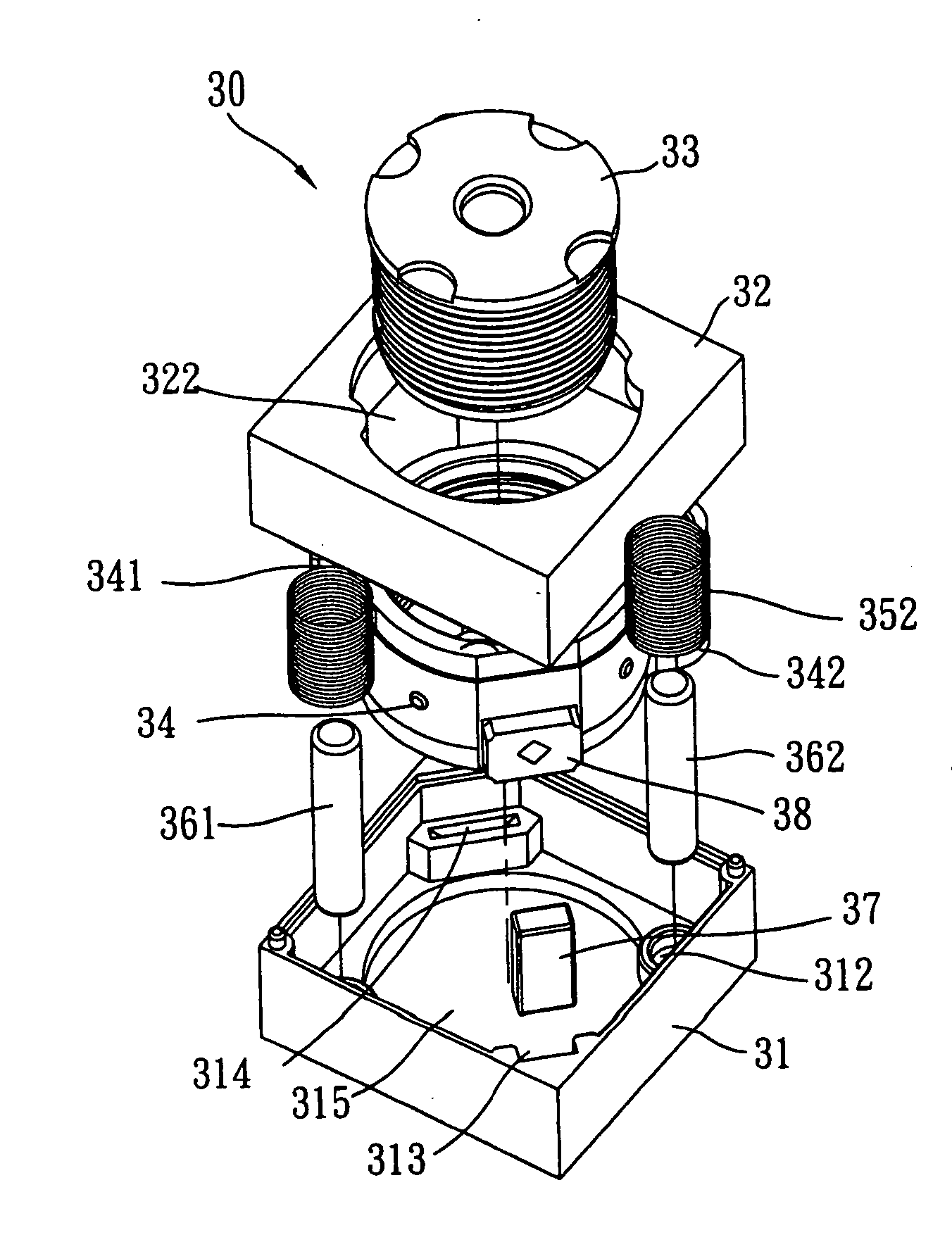
[0010] Another object of the present invention is to provide a miniature linear motor driving device, characterized in which a driving coil is wound around the periphery of a magnetic guide rail in a non-contact manner and a holder is linked to either the magnetic guide rail or the driving coil. Based on the principle of electromagnetic induction, when current is applied to the driving coil, the magnetic action between the magnetic guide rail and the driving coil causes displacement motion between them, thereby driving the movement of holder, and the magnetic guide rail also provides guidance for the direction of displacement. As such, the driving device does not need to have an additional guide rail arranged, thereby further reducing the number of elements used, reducing the size and simplifying the configuration of device. In addition, as the magnetic flux lines of driving coil converge directly on the magnetic guide rail, better driving efficiency is achieved and more power is saved.
[0011] Yet another object of the present invention is to provide a miniature linear motor driving device, which, by using a magnetic sensor to detect the position of holder as position feedback during holder displacement, offers the advantages of smaller size, lower cost, and precision positioning.
[0012] A further object of the present invention is to provide a miniature linear motor driving device which is configured with a unique prepressed spring that when the holder is at the initial position, the prepressed spring engages the holder to secure it in place, when the holder starts to move, the prepressed spring bends and deforms to apply a predetermined pressure on the holder to further stabilize it in the course of moving.

Problems solved by technology

Such design has the deficiencies of complicated mechanical configuration, time-consuming assembly, bulkiness and high cost.
Most seriously, it consumes a large amount of power.
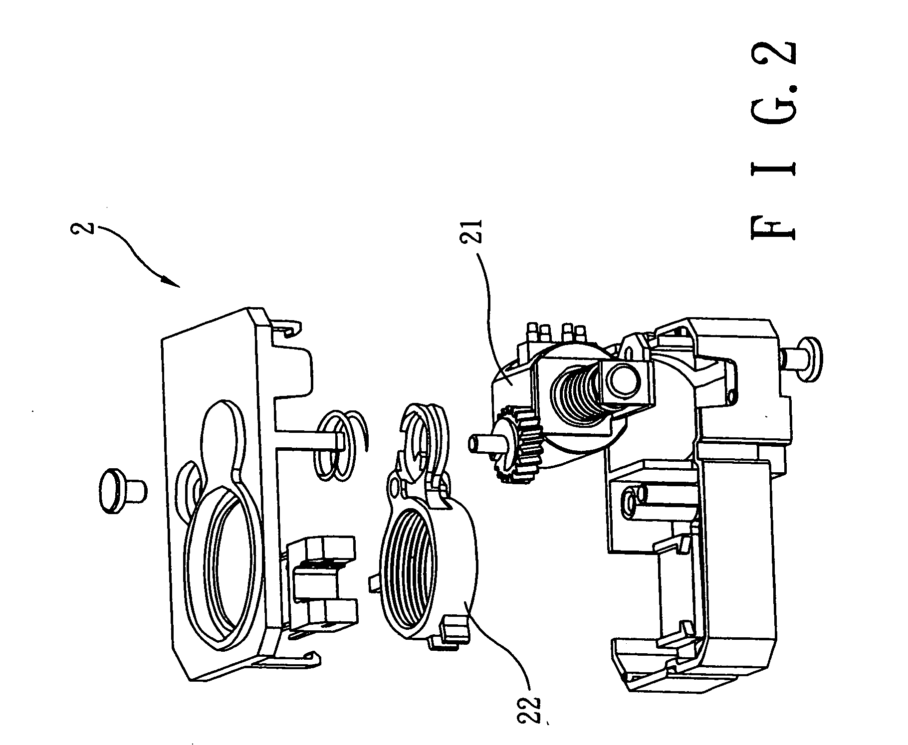
Such design offers the advantage of open-loop control, but the whole mechanism takes considerable space, which renders the miniaturization of modules difficult.
Also the longer response time of stepping motor leads to greater vibration and noise during operation, which is the biggest drawback for this kind of actuator.
But the “high voltage” operation, the brittleness of piezoelectric material, and ease of wear pose considerable problem for photographic devices when considering piezoelectric actuator for driving the lens.
But it consumes more power and employs close-loop control, therefore having room for improvement.

Method used


Image

  • Miniature linear motor driving device and auto-focus lens device using the same
  • Miniature linear motor driving device and auto-focus lens device using the same
  • Miniature linear motor driving device and auto-focus lens device using the same

Examples


Embodiment Construction

[0025] The miniature linear motor driving device according to the invention utilizes primarily the principle of electromagnetic induction, which, through the magnetic action between the magnetic guide rail and the driving coil, causes the driving coil to move. When current is applied to the driving coil, the coil moves in one direction along the guide rail when the electromagnetic force generated thereof attracts the magnetic force of the magnetic guide rail; conversely, by applying inverse current to the driving coil, the electromagnetic force induced thereof and the magnetic force of the magnetic guide rail would repel each other, and the coil would move in another direction along the guide rail. Based on such phenomenon, the holder, which has driving coil assembled thereon, would be driven by the driving coil to achieve the purpose of moving the lens unit mounted on the holder.

[0026] FIGS. 3˜7 disclose a preferred embodiment of the miniature linear motor driving device according...


PUM


Abstract

A miniature linear motor driving device for lens focusing is disclosed. Said driving device comprises a holder, at least a driving coil, and at least a magnetic guide rail. The holder is disposed with at least a guide hole and can be used to accommodate the lens unit. The driving coil is wound around the periphery of guide hole. The magnetic guide rail is secured through the guide hole and formed with a first polarity and a second polarity opposing each other at each end. The holder engages in linear displacement along the magnetic guide rail. A predetermined magnetic force is generated by supplying current to said driving coil, which interacts with the polarities at both ends of magnetic guide rail to push the holder to move linearly along the magnetic guide rail.

Description

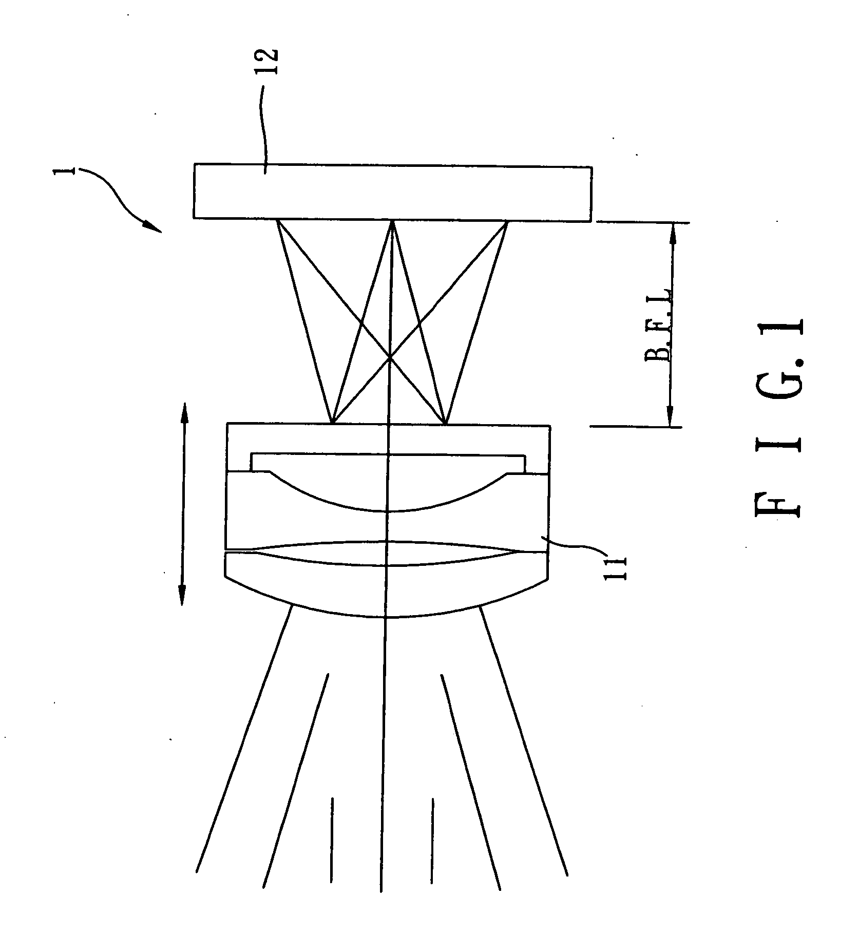
BACKGROUND OF INVENTION [0001] 1. Field of the Invention [0002] The present invention relates to a miniature linear motor driving device for use in auto-focus lens unit, more particularly a driving device suitable for application in lens unit that uses linear motor as power source for focusing and supplies power by means of the electromagnetic action between a driving coil and magnetic guide rail disposed therethrough. [0003] 2. Description of the Prior Art [0004] As shown in FIG. 1, a standard camera 1 comprises a lens set 11, a sensor 12 and a focusing mechanism (not shown in the figure). The lens set 11 forms an image on sensor 12 by refracting the light rays from an object. If the distance between lens set 11 and sensor 12 is fixed (i.e. a fixed lens), the lens can only show clearly objects at its hyperfocal distance (e.g. 2-3 meters away). For the camera to shoot objects clearly at varying distances (for example at a close distance), the distance between lens set and sensor mus...

Claims


Application Information

Patent Timeline
IPC IPC(8): H02K41/00G02B15/14
CPCH02K41/0352G02B7/08
Inventor HO, WEN JENCHANG, CHI LONE
Owner POWERGATE OPTICAL INC
Learn More