Dual laser beam guidance and parking device

a laser beam guidance and parking device technology, applied in the direction of instruments, using reradiation, transportation and packaging, etc., can solve the problems of limited space for opening the vehicle door, damage to the vehicle door when opened, and becoming increasingly difficult to properly park the vehicle in the desired location, etc., to achieve simple and efficient, high accuracy in vehicle positioning, and simple design

Inactive Publication Date: 2007-03-01
HERBERT WILLIAM J +2
View PDF16 Cites 36 Cited by
  • Summary
  • Abstract
  • Description
  • Claims
  • Application Information

AI Technical Summary

Benefits of technology

[0020] The present invention provides methods and apparatuses for a new and improved vehicle positioning method and also temperature compensating dual laser devices to achieve high accuracy in vehicle positioning. It is simple in design and overcomes the aforementioned disadvantages of all prior art. The difficulties inherit in the prior art are therefore overcome in a way that is simple and efficient, while providing improved and more advantageous results. The present invention utilizes two laser beams that are emitted from the inside of a vehicle such as the dash, windshield, rearview mirror bracket, rear window, radar detector or from the outside of a vehicle in an enclosed exterior location such as the headlamp assemblies, rear view mirrors, or taillight assemblies. Since the broad temperature ranges that can be experienced by the vehicle ranging from sub-freezing to approximately 150° F. can significantly affect the longitudinal calibration point, one important aspect of the present invention, is a new dual laser vehicle positioning device that is temperature compensating either by its inherent design or by the use of materials with different thermal expansion coefficients, resulting in a broad use temperature range for vehicles and high accuracy of longitudinal and lateral distance control even when vehicle positioning is done in hot summer or cold winter conditions.
[0021] By using a method of equidistantly aiming the two temperature compensated converging laser beams horizontally around a vertical line placed on a surface point forward or rearward as a vehicle reaches the entrance to the pre determined parking position and maintaining that equidistant spacing as the vehicle moves forward or rearward into the parking position, lateral positioning of the vehicle is obtained. When the two lasers dots converge on the forward or rearward vertical line, longitudinal positioning of the vehicle is achieved. This method has a significant advantage over other art since the two laser dots are much more visible in entering a parking position within an enclosed parking space or within a shroud enclosing a vertical line in bright sunlight conditions, are extremely easy for the vehicle operator to visually use to achieve the desired parking position, and are inherently visually easier to accurately align the two laser outputs on the vertical line and thus achieve higher accuracy in the vehicle parking position.
[0022] The present invention can also be utilized to precisely position a towing vehicle to a towed vehicle for engagement of the trailer hitch to the ball of the towed object by mounting the dual lasers on the inside back window of the vehicle. In bright sunlight conditions, where the laser dots may not be adequately visible, an enclosed shroud placed over the vertical line is used to shield the vertical line from the bright light conditions allowing the vehicle operator visibility for vehicle positioning.

Problems solved by technology

As vehicle sizes and garage storage of miscellaneous items such as lawn mowers, tools, bicycles, waste containers, etc. have increased, it has become increasingly difficult to properly park vehicles in the desired location.
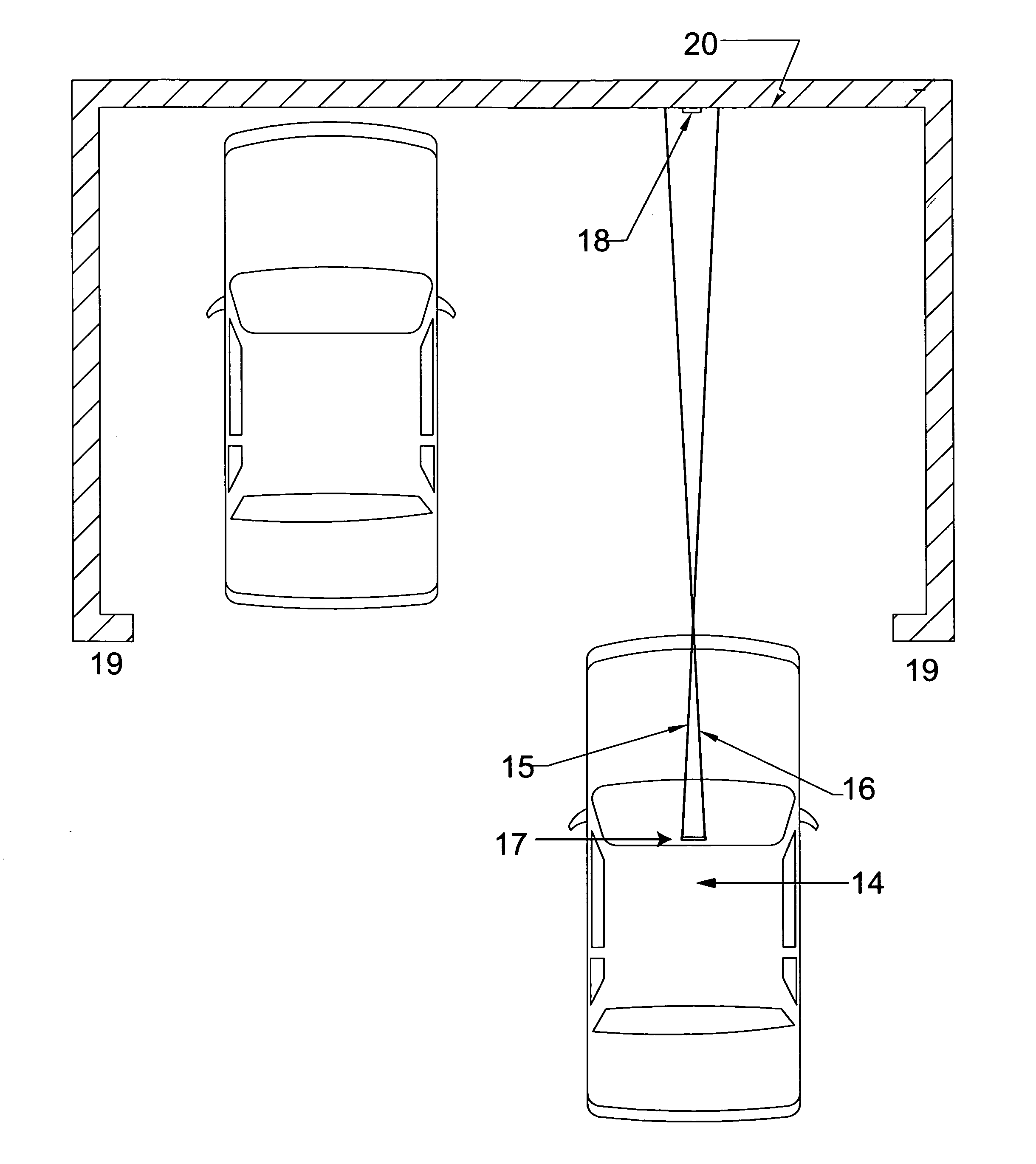
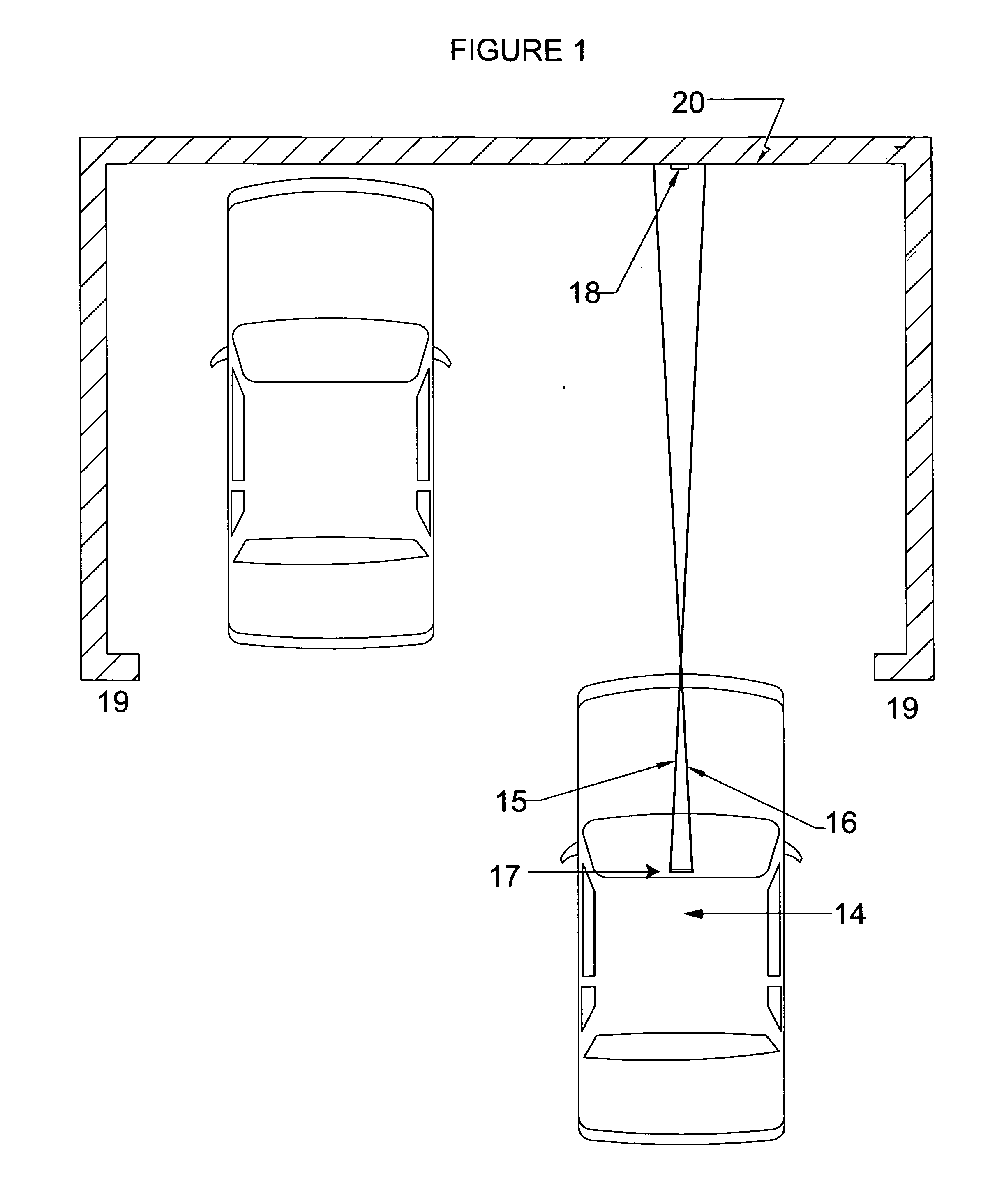
It is common for the driver of a vehicle to park their vehicle in a non-optimum position that result in the vehicle being positioned too close to the garage wall or even damaging it, parking too far away from the garage wall thus preventing the garage door from closing requiring repositioning the vehicle, or parking too far left or right laterally in the garage resulting in limited space to open the vehicle doors or causing damage to the vehicle doors when opened.
Each of these devices requires contact with the vehicle and are obstacles when the vehicle is not parked in the garage.
In addition, these devices do not provide continuous guidance to the driver to achieve lateral centering within the parking space desired.
However, these devices require inconvenient ceiling installation and do not guide the vehicle into the proper parking position for both distance from the garage wall and lateral centering within the parking space.
By the time that the laser dot is seen by the vehicle driver, insufficient distance is left to adjust the vehicle position for proper lateral centering location.
However, such a device and method has the drawbacks of requiring a wall mounting of the laser device, placing a target on the windshield of a vehicle, and maneuvering the vehicle such that the laser beam can be seen by the vehicle driver at the entrance to a parking position, which is extremely difficult, especially in bright sunlight conditions on a transparent windshield surface.
However, no accurate lateral guidance can be provided by using a single laser if the vehicle approaches the garage wall at an angle.
However, the intersection of the laser line and dot do not provide continuous guidance to the vehicle operator to achieve the precise parking position desired.
Also, achieving sufficient brightness of two line laser outputs for proper observation by the driver is a major issue in bright sunlight conditions.
In addition, this device is significantly more complex, requires mounting on the garage ceiling, and consumes significantly more power than the present invention.
When the dot and line converge longitudinal distance control is achieved, but vehicle lateral positioning is not achieved.
However, this patent does not teach that the two laser outputs must be equidistantly aligned on both sides of the target at all times as the vehicle is moved forward towards the target to achieve exact lateral centering and longitudinal distance positioning.
The cited patent also does not teach that accuracy of the laser convergence point can be strongly affected by any thermal expansion or contraction of the actual device or attachment points to the vehicle used with the lasers.
Thermal expansion within the device holding the two lasers, for example in hot locations, could separate the two lasers and greatly affect their point of convergence thus significantly compromising distance control to the electric docking station.
A—Slight misalignment of the two optical sources in the Capik patents can result in the two optical sources not aligning and therefore not producing a third color to indicate correct positioning has been achieved.
C—The use of the a longitudinal target or a led sensor plate as shown in FIG. 9 of Capik patents result in an increases the cost / complexity and is not as accurate or as visually easy to use by the vehicle operator as in the current invention of this application.
Neither of these methods provide continuous maneuvering guidance or final vehicle position to the vehicle operator since, in bright sunlight, unless a shroud is used over the target, the laser beams are extremely difficult to see in sunlight.
The Capik patents also do not teach that laser devices mounted internally within a vehicle are not subject to the variety of conditions that can render unprotected externally mounted laser devices ineffective or undesirable such as dirty laser lens from outside dust, rain, ice, vandalism, or theft of the laser devices utilized.
However, this method requires the vehicle driver to make an estimate on when the width between the dots is at the desired distance of the vehicle from the forward wall and is, therefore, not highly accurate for distance control from the forward surface.
However, this method requires the vehicle driver to both look forward and sideward to verify the vehicle position and also requires a side wall to be present, which is not generally available in parking garages or parking decks.

Method used


Image

  • Dual laser beam guidance and parking device
  • Dual laser beam guidance and parking device
  • Dual laser beam guidance and parking device

Examples


Embodiment Construction

[0036] Referring now to the drawings wherein the showings are for purposes of illustrating a preferred embodiment of the invention only and not for purposes of limiting the same;

[0037]FIG. 1 shows a top view of a vehicle, 14, projecting two laser beams, 15 and 16 that are guiding the vehicle driver at the entrance of a parking garage with sidewalls, 19, and forward wall, 20. The two laser beams, 15 and 16 must be guided by the vehicle operator such that they remain equidistantly placed around the vertical line, 18, throughout the parking approach, as shown in FIG. 4. The dual laser beam device, 17, can be mounted to the windshield, the dashboard of vehicle, 14, or incorporated into the rear view mirror mounting bracket.

[0038]FIG. 2 shows the vehicle, 14, with the dual laser device, 17, projecting two laser beams, 15 and 16, such that the laser beams, 15 and 16, have converged on the vertical line, 18, as shown in FIG. 5 thus achieving the pre-determined location.

[0039]FIG. 3 show...


PUM


Abstract

A vehicle guidance and parking system that continuously guides the operator of a vehicle to a pre-determined parking position by using two laser beams impinging on a forward or rearward surface. The two lasers beams project to a substantially vertical surface to which a vertical line has been applied and the vehicle is guided by the operator such that the two laser beams are kept equidistantly horizontally centered around the line during the vehicle approach to maintain the correct lateral position in the pre-determined parking position. When the two laser beams converge on the vertical line, the vehicle is longitudinally positioned to the pre-determined parking position. Temperature compensation, due to the wide temperature of potential use range, is provided by the laser emitting device used in the vehicle guidance and parking system. A light blocking shroud is used around the vertical line in bright sunlight conditions when necessary to improve the visibility of the two laser beam outputs for vehicle maneuvering.

Description

[0001] This application claims priority from U.S. Ser. No. 60 / 711,331, entitled DUAL LASER BEAM GUIDANCE AND PARKING DEVICE, filed Aug. 25, 2005.STATEMENT REGARDING FEDERALLY SPONSORED RESEARCH OR DEVELOPMENT [0002] Not applicable. 1. BACKGROUND OF THE INVENTION [0003] A. Field of Invention [0004] This invention pertains to temperature compensating dual laser devices and methods for guiding vehicles to accurate pre-determined locations using converging laser beams emitting from inside a vehicle interior or an enclosed vehicle exterior location. The pre-calibrated location includes both longitudinal distance from a surface vertical line forward or rearward from the vehicle and also centering the vehicle laterally whereby the longitudinal distance accuracy is controlled by an automatic temperature compensating laser emitting device. [0005] B. Description of the Related Art [0006] It is well known to use a number of different devices to aid the driver of a vehicle in parking the vehicl...

Claims


Application Information

Patent Timeline
Patent Type & Authority Applications(United States)
IPC IPC(8): G08G1/14
CPCG01S7/497G01S17/46G08G1/168G08G1/161G01S17/93
Inventor HERBERT, WILLIAM J.MCFARLAND, STEPHENDECHIARA, ANTHONY
Owner HERBERT WILLIAM J
Why Eureka
Try Eureka