Processing of tank signal in radar level gauge system

a technology of radar level gauge and tank signal, which is applied in the direction of using reradiation, measurement devices, radio wave reradiation/reflection, etc., can solve the problems of complicated rlg measurement process, not necessarily optimal, and typical optimized signal processing

Active Publication Date: 2007-03-01
ROSEMOUNT TANK RADAR
View PDF26 Cites 25 Cited by
  • Summary
  • Abstract
  • Description
  • Claims
  • Application Information

AI Technical Summary

Benefits of technology

[0006] It is an object of the present invention to provide information about conditions in specific regions of the tank, without the need for additional sensors.

Problems solved by technology

However, the signal processing is typically optimized in terms of general precision in the entire tank, and is not necessarily optimal in all areas of the tank.
In an RLG measurement process can be complicated or even made impossible, when the surface reflection occurs in this near zone, which can be in the range of 0 m to 2 m depending on the type of microwave signal used.
The problems are caused by an interfering reflection caused by the transition between a signal transfer medium and the emitter / receiver in the tank, in combination with the limited bandwidth limiting the resolution.
Although the normal measurement processing may be adapted to provide accurate measurements also in the top of the tank (referred to as the near zone), such a redundant sensor system is required by authorities in many countries

Method used


Image

  • Processing of tank signal in radar level gauge system
  • Processing of tank signal in radar level gauge system
  • Processing of tank signal in radar level gauge system

Examples


Embodiment Construction

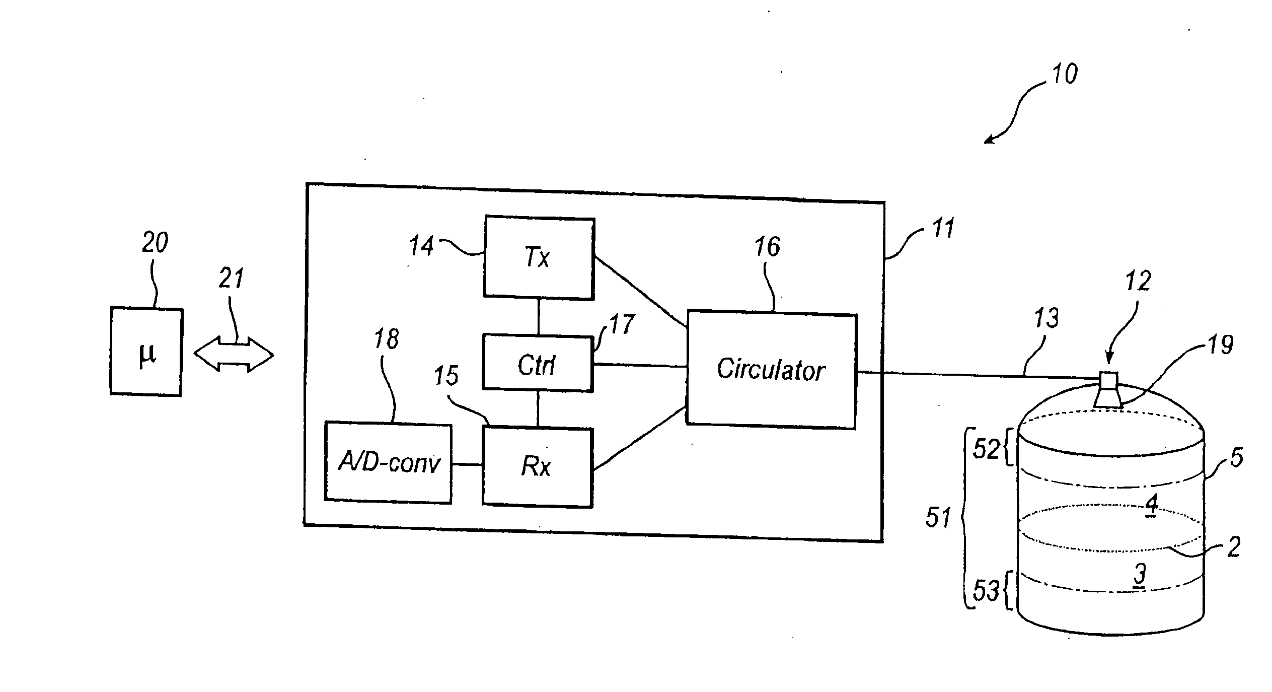
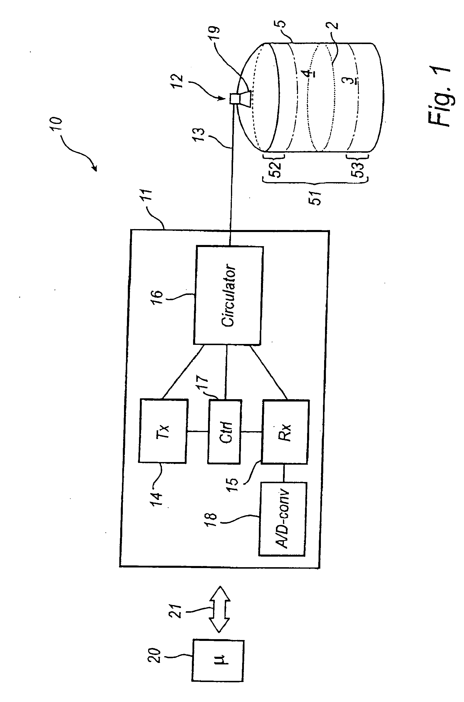
[0027]FIG. 1 shows a schematic block diagram of a radar level gauge (RLG) 10, in which the present invention has been implemented. The gauge 10 is arranged to perform measurements of a process variable in a tank, such as th level of an interface 2 between two (or more) materials 3, 4 in the tank 5. Typically, the first material 3 is a content stored in the tank, e.g. a liquid such as gasoline, while the second material 4 is air or some other atmosphere. In that case, the RLG will enable detection of the level of the surface of the content in the tank. Note that different tank contents have different impedance, and that the electromagnetic waves will only propagate through some materials in the tank. Typically, therefore, only the level of a first liquid surface is measured, or a second liquid surface if the first liquid is sufficiently transparent.

[0028] The RLG 10 comprises a microwave controller 11, a microwave emitter / receiver 12, and a signal transfer medium 13 connecting the e...


PUM


Abstract

A method and a system for processing a reflected microwave signal generated by a radar level a gauge system arranged to transmit microwaves towards the material in the tank, and receive a reflection of said microwave signal as a tank signal. The tank signal is processes by a plurality of processes, each process being adapted to determine a process variable in a specific region of the tank, each specific region corresponding to a predefined propagation distance range. Such multi-processing of the received tank signal has the advantage that each process can be optimized to that particular region of the tank. More specifically, a process concerned with a particular region of tank only needs to treat a portion of the tank signal.

Description

FIELD OF THE INVENTION [0001] The present invention relates to radar level gauge (RLG) systems. In such systems, microwaves are emitted into a tank and a reflected tank signal is received. Based on signal processing of this reflected signal, a process variable such as the level of a content in the tank can be determined BACKGROUND OF THE INVENTION [0002] Such RLG systems typically include a signal generator, means to emit the signal into the tank, and a receiver for receiving the reflected tank signal. The received signal can for example be a time domain reflectometry (TDR) signal or a frequency domain signal, such as a frequency modulated continuous wave (FMCW) signal. The received signal typically comprises at least a surface reflection (echo) caused by an interface between different materials in the tank, typically but not necessarily a liquid surface. Normally, the received signal also includes various interfering reflections caused e.g. by the bottom and walls of the tank or th...

Claims


Application Information

Patent Timeline
Patent Type & Authority Applications(United States)
IPC IPC(8): G01S13/08G01S7/40
CPCG01F23/284G01F23/00G01S13/08
Inventor LARSSON, LARS OVEODER, MARIANNEVILHELMSSON, KATARINAWESTERLING, JAN
Owner ROSEMOUNT TANK RADAR
Why Eureka
Try Eureka