Method and apparatus for visual background subtraction with one or more preprocessing modules

a technology preprocessing modules, applied in the field of visual background subtraction techniques, can solve problems such as image jitter, adversely affecting the efficacy of this class of techniques, and changes in camera responses

Inactive Publication Date: 2007-03-01
IBM CORP
View PDF13 Cites 59 Cited by
  • Summary
  • Abstract
  • Description
  • Claims
  • Application Information

AI Technical Summary

Benefits of technology

[0013] Generally, methods and apparatus are provided for visual background subtraction using one or more preprocessing modules. According to one aspect of the invention, an image signal that has undergone previous corruption by one or more effects is processed. The one or more effects in the received image signal are detected and one or more blocks are selectively enabled to preprocess the image signal to compensate for the detected one or more effects. Thereafter, visual analysis, such as identifying one or more objects in the preprocessed image signal, is performed on the preprocessed signal using background subtraction.

Problems solved by technology

Unfortunately, there are numerous factors that can adversely impact the efficacy of this class of techniques.
Such disturbances include changes in camera responses due to automatic gain and color-balance corrections, image jitter due to vibration or wind, perceptually-masked artifacts due to video compression or cabling inadequacies, and varying object size due to lens distortion or imaging angle.
Some of these problems have simple solutions, but they are not optimal.
While video can be transmitted and recorded in an uncompressed state, the required bandwidth and disk-storage space increases costs significantly.
Although it is possible to correct imaging geometry, this is difficult to cope with in practice because it involves moving cameras to optimal viewing locations.
Such locations may be inconvenient (e.g., requiring significantly longer cable runs) or not feasible (e.g., above the ceiling level).
The solutions to other problems are not as straightforward.
However these solutions require changing the cameras that are already installed.
Also, these solutions are typically bulkier than an ordinary fixed camera and hence may be difficult to install in some locations.
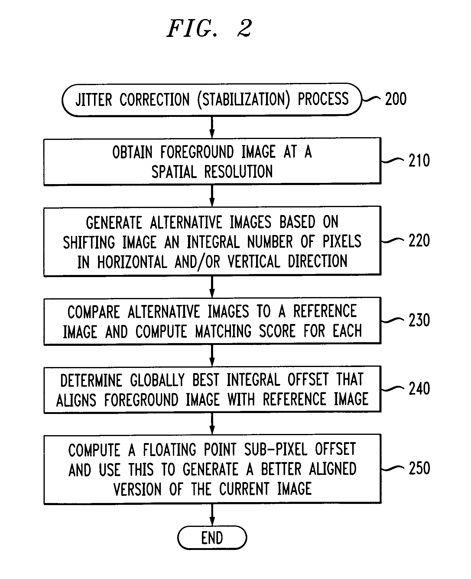
However, these pixel shifts are typically integer pixel shifts that are not accurate enough to remove all the artifacts generated by background subtraction.
However, this analysis is mathematically complicated thus necessitating either a lower video frame rate or a more expensive computation engine.
Unfortunately, these corrections can impair machine analysis of the images because there are frame to frame variations that are not due to any true variation in the imaged environment.
Some cameras allow AGC and AWB to be disabled, however, this may not be true for all (possibly legacy) cameras in a video surveillance system.
Also, it is sometimes desired to analyze previously recorded material where the source camera and its parameters can not be controlled retroactively.
While it is possible to correct exposure and color balance using techniques such as histogram stretching or contrast stretching, these whole-image methods can be confused if the content of the scene changes.
Unfortunately, when separating these two signals to reconstruct the image representation, sharp changes in the intensity signal can be interpreted as color shifts.
This can happen due to inadequate band limiting of the intensity signal at the source, poor “comb” filtering at the receiver, or nonlinear dispersion in the transmission medium (typically coax cable).
This aliasing results in strobing color rainbow patterns around sharp edges.
This can be disadvantageous for computer vision systems that need to know the true colors of regions, or for object detection and tracking systems based on background subtraction which may erroneously interpret these color fluctuations as moving objects.
However, this processing removes potentially valuable information from the image.
However, this approach is sub-optimal in that the boundaries of objects (and sometimes even their identities) can be obscured by such blurring.
Unfortunately, many times video has been subject to a lossy compression method, such as MPEG (especially if it has been digitally recorded), in which case the exact details of the original waveform cannot be recovered with sufficient fidelity to permit this re-processing.
A further problem is that video images often contain “noise” that is annoying to humans and can be even more detrimental to automated analysis systems.
Unfortunately, this tends to wash out sharp edges and obscure region textures.
Median-based filtering attempts to preserve sharp edges, but still corrupts texture (which is interpreted as noise) and leads to artificially “flat” looking images.
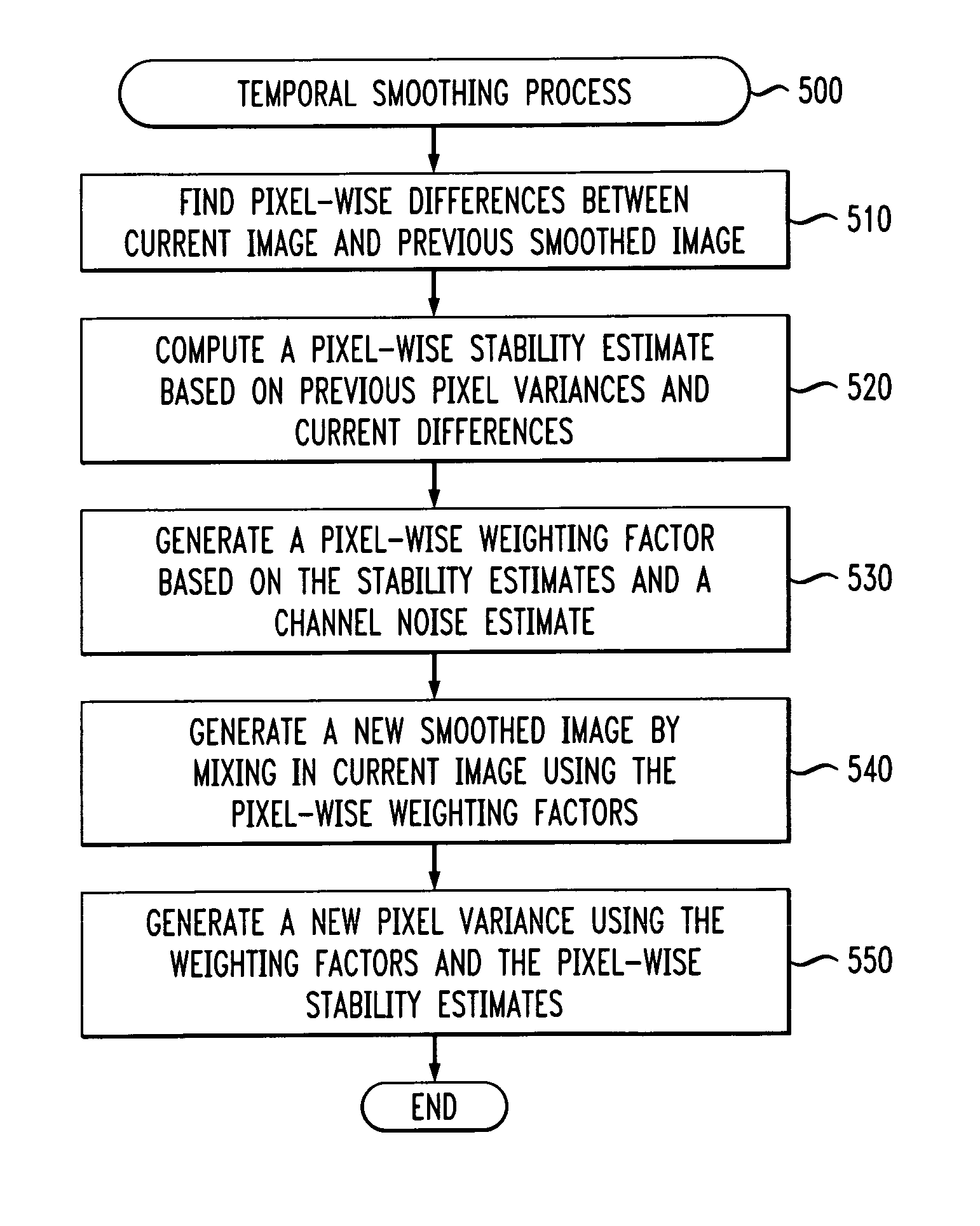
This works well for largely stationary images, but moving objects often appear ghostly and leave trails behind.
Yet another difficulty is that background subtraction operates by comparing the current image with a reference image and highlights any pixel changes.
Unfortunately, while often the desired result is the delineation of a number of physical objects, shadow regions are typically also marked because the scene looks different here as well.
Unfortunately, this method requires the computation of hue, which is typically expensive because it involves trigonometric operators.
Moreover, hue is unstable in regions of low saturation or intensity (e.g., shadows).
Finally, the derived hue is very sensitive to the noise in each color channel (the more noise, the less reliable the estimate).

Method used


Image

  • Method and apparatus for visual background subtraction with one or more preprocessing modules
  • Method and apparatus for visual background subtraction with one or more preprocessing modules
  • Method and apparatus for visual background subtraction with one or more preprocessing modules

Examples


Embodiment Construction

[0024] The present invention provides methods and apparatus for visual background subtraction with one or more preprocessing modules. An input video stream is passed through one or more switchable, reconfigurable image correction units before being sent on to a background subtraction module or another visual analysis system. Depending on the environmental conditions, one or more modules can be selectively switched on or off for various camera feeds. For instance, an indoor camera generally does not require wind correction. In addition, for a single camera, various preprocessors might only be invoked at certain times. For example, at night, the color response of most cameras is poor in which case they revert to essentially monochrome images. Thus, during the day, the signal from this camera might be processed to ameliorate the effect of chroma filtering (e.g., moving rainbow stripes at sharp edges) yet this module could be disabled at night.

[0025] The present invention copes with ea...


PUM


Abstract

Methods and apparatus are provided for visual background subtraction using one or more preprocessing modules. One or more effects are detected in a received image signal and one or more blocks are selectively enabled to preprocess the image signal to compensate for the detected one or more effects. Visual analysis is then performed on the preprocessed signal using background subtraction. A spatially-variant temporal smoothing of the image signal is also disclosed. The spatially-variant temporal smoothing can be achieved by the mixing of a new intensity value with a previous intensity time-average as determined by a weighting matrix. The mixing can be influenced by a dynamic bias term that is a real-time estimate of a variance at the pixel, such as a degree of change, and the weighting can be determined by a relative stability of an observed value compared to a stability of the time-average.

Description

FIELD OF THE INVENTION [0001] The present invention relates generally to imaging processing techniques, and, more particularly, to techniques for visual background subtraction. BACKGROUND OF THE INVENTION [0002] Background subtraction is a popular technology for finding moving objects in images of an environment. Unfortunately, there are numerous factors that can adversely impact the efficacy of this class of techniques. Such disturbances include changes in camera responses due to automatic gain and color-balance corrections, image jitter due to vibration or wind, perceptually-masked artifacts due to video compression or cabling inadequacies, and varying object size due to lens distortion or imaging angle. [0003] Some of these problems have simple solutions, but they are not optimal. While video can be transmitted and recorded in an uncompressed state, the required bandwidth and disk-storage space increases costs significantly. Similarly, lens distortions can be remedied by purchasi...

Claims


Application Information

Patent Timeline
Patent Type & Authority Applications(United States)
IPC IPC(8): G06K9/40
CPCG06T5/50G06T7/2053G06T5/002G06T5/006H04N1/6027G06T2207/10024G06T2207/20144G06T2207/20182H04N1/407G06T5/007G06T7/254G06T7/194
Inventor CONNELL, JONATHAN H.
Owner IBM CORP
Why Eureka
Try Eureka