
Device for generating X-ray or XUV radiation

Inactive Publication Date: 2007-03-08
COMET
View PDF9 Cites 17 Cited by
  • Summary
  • Abstract
  • Description
  • Claims
  • Application Information

AI Technical Summary

Benefits of technology

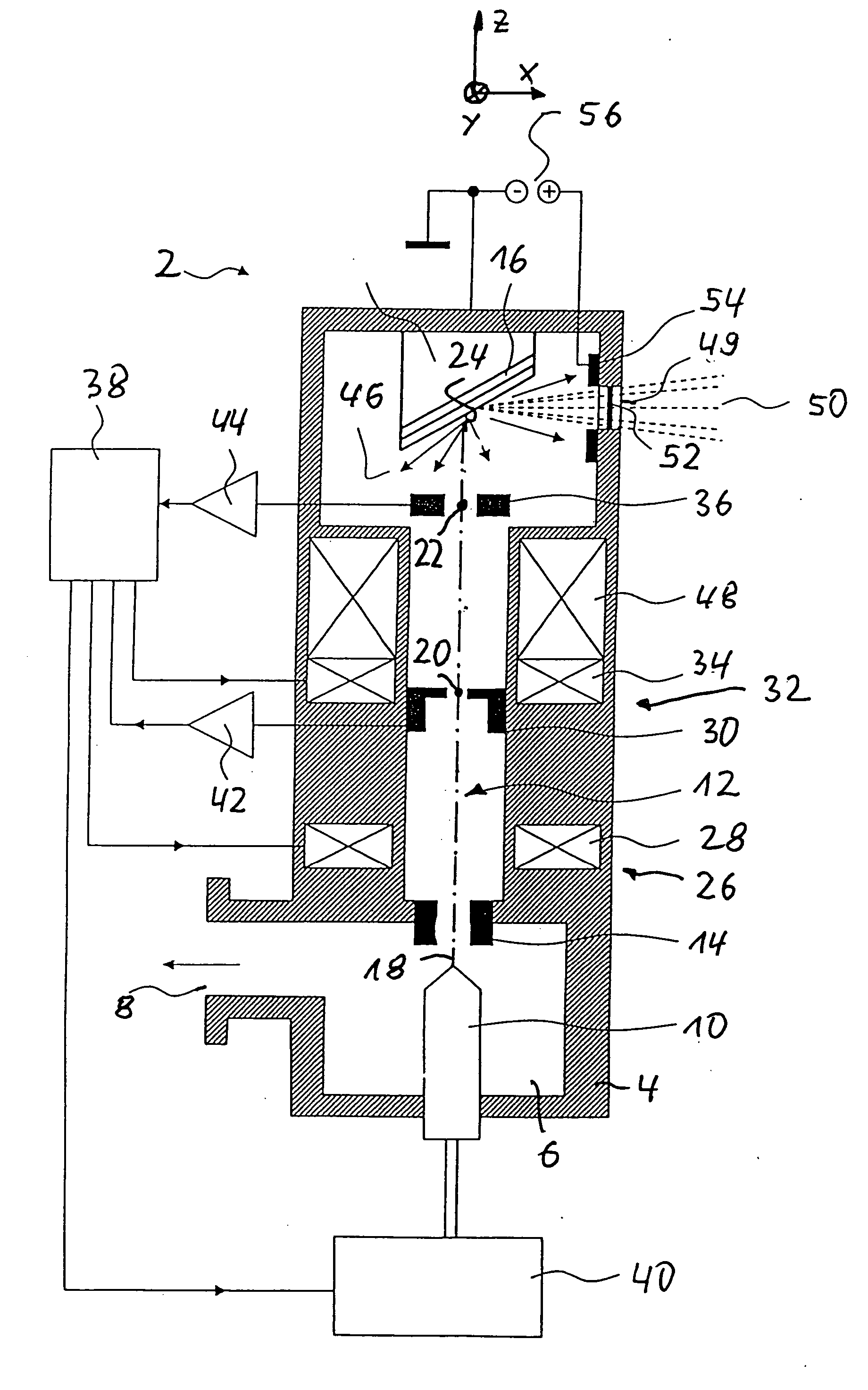
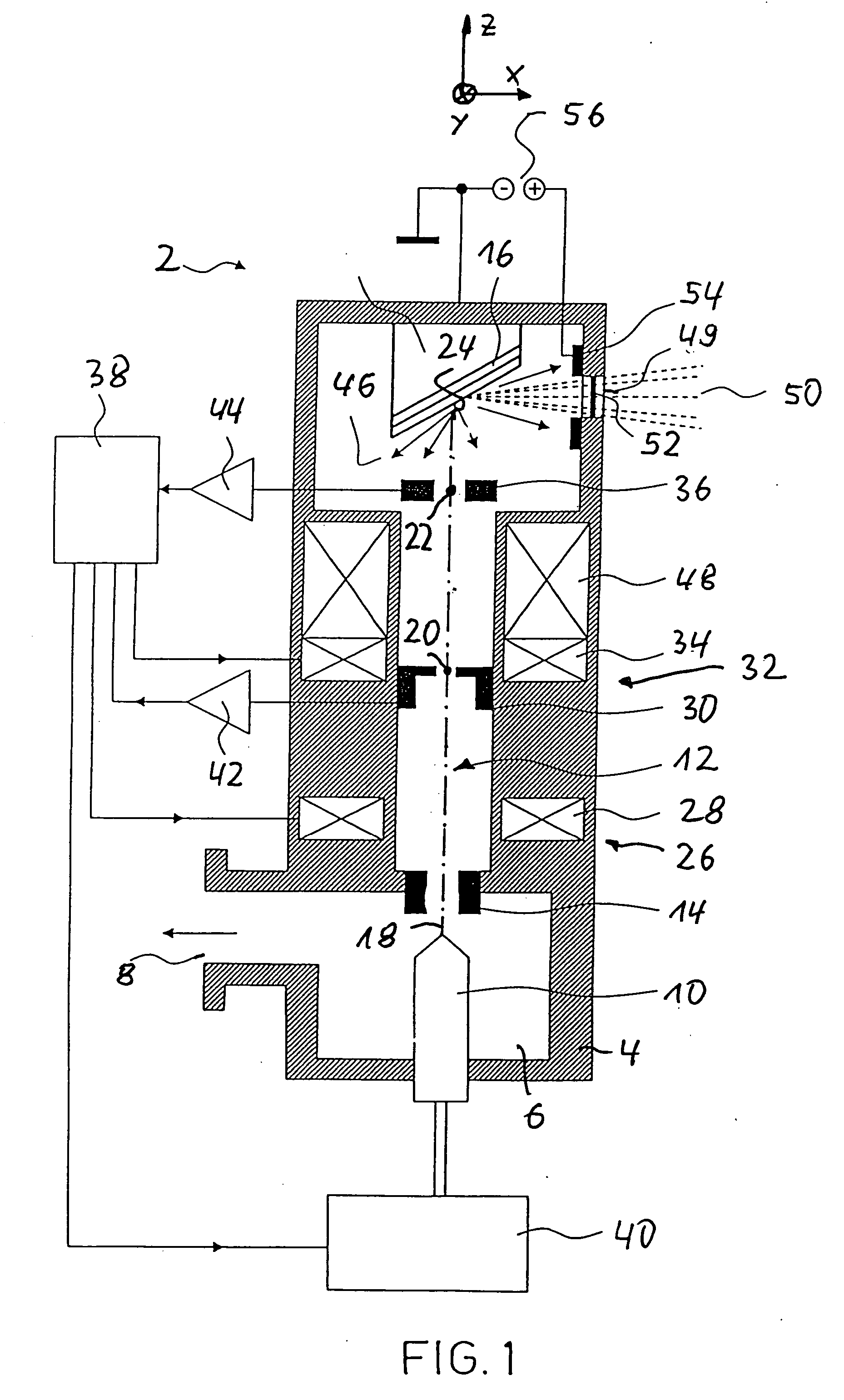
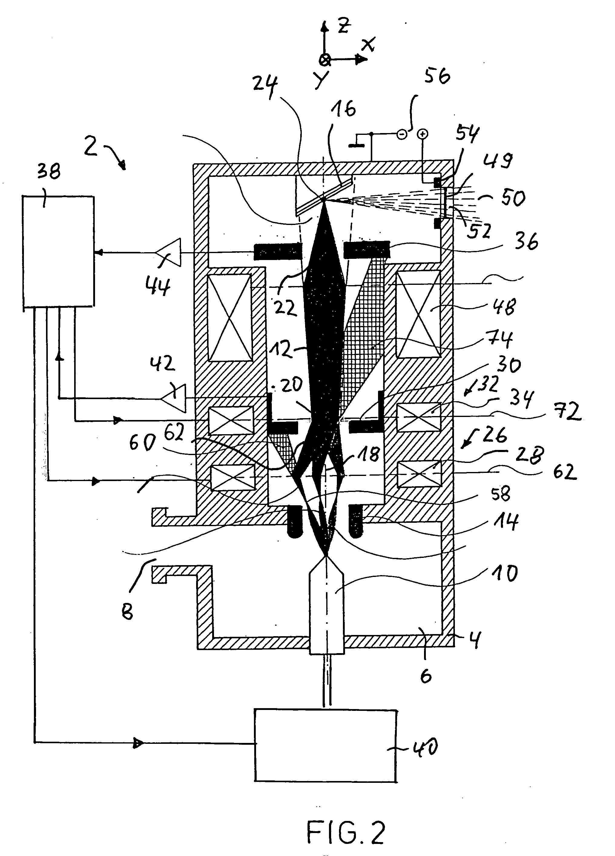
[0006] An object of this invention is to provide a device of the type for generating X-ray or XUV radiation including a device for directing a particle beam of electrically charged particles towards a target, and including a deflection device for deflecting the particle beam in such a way that the central axis of the particle beam passes through a first point of deflection and a second point of deflection located at a distance from the first point of deflection in the direction of propagation of the beam. The deflection device includes a first deflector for deflecting the particle beam in such a way that the central axis of the particle beam passes through the first point of deflection, and a second deflector at a distance from the first deflector in the direction of propagation of the beam of the particle beam, in order to deflect the particle beam in such a way that the central axis of the particle beam passes through the second point of deflection, and the particle beam can be deflected by the deflectors with respect to one point of deflection independently from a deflection with respect to another point of deflection. The object being that the deviations of the point of impact of the particle beam on the target from a specified point of impact are reduced, and that the local stability of the particle beam thus is improved in terms of its point of impact on the target.

Problems solved by technology

A disadvantage of the known devices is that a deviation of the point of impact of the particle beam on the target from a specified point of impact will impair the image quality of the images generated by way of irradiation of components and result in errors of measurement when performing measuring and adjustment functions, as well as adjustment tasks.

Method used


Image

  • Device for generating X-ray or XUV radiation
  • Device for generating X-ray or XUV radiation
  • Device for generating X-ray or XUV radiation

Examples


Embodiment Construction

[0034]FIG. 1 shows an example of an inventive device 2, which in this embodiment serves to generate XUV radiation. The device 2 is embodied in the form of an X-ray tube, and includes a housing 4, the interior 6 of which is embodied as a vacuum chamber and can be evacuated by way of a vacuum pump (not shown) via an opening 8.

[0035] Inside the vacuum chamber 6, a particle source 10 is provided for generating a particle beam of electrically charged particles, wherein in this embodiment the electrically charged particles are formed by electrons discharged from a cathode. The electrons are accelerated to form a particle beam 12 by way of an annular anode 14 in the direction towards a target 16, which in this embodiment is shaped as a layer target. When impacting the target 16, the electrons forming the particle beam 12 are slowed down, as a result of which radiation (Bremsstrahlung) is created, the spectrum of which depends on the energy of particles and the chemical structure (atomic n...


PUM


Abstract

Device for generating X-ray or XUV radiation includes a device for directing a particle beam of electrically charged particles towards a target. A deflection device for deflecting the particle beam is such that the central axis of the particle beam passes through a first point of deflection and a second point of deflection located at a distance from the first point of deflection in the direction of propagation of the beam. The first and second points of deflection lie on an axis in line with a determined or determinable point of impact of the particle beam with the target. The particle beam can be deflected by the deflection device in the direction of propagation of the beam in the region of one point of deflection independently from of a deflection of the particle beam in the region of the other point of deflection.

Description

CROSS-REFERENCE TO RELATED APPLICATIONS [0001] This application claims priority of German Application No. 10 2005 041 923.2, filed Sep. 3, 2005, and which is incorporated herein by reference. FIELD OF THE INVENTION [0002] This invention relates to a device for generating X-ray or XUV radiation including a device for directing a particle beam of electrically charged particles towards a target, and including a deflection device for deflecting the particle beam in such a way that the central axis of the particle beam passes through a first point of deflection and a second point of deflection located at a distance from the first point of deflection in the direction of propagation of the beam. The deflection device includes a first deflector for deflecting the particle beam in such a way that the central axis of the particle beam passes through the first point of deflection, and a second deflector at a distance from the first deflector in the direction of propagation of the beam , in ord...

Claims


Application Information

Patent Timeline
IPC IPC(8): G01J3/10
CPCH01J35/02H01J35/30H01J35/14H01J35/147H01J35/153G21K1/087G21K1/08
Inventor REINHOLD, ALFRED
Owner COMET
Learn More