Control system for doubly fed induction generator

a control system and induction generator technology, applied in the control of electric generators, machine/engines, dynamo-electric converters, etc., can solve problems such as grid voltage variations that can present problems, and achieve the effect of reducing the rotor curren

Active Publication Date: 2007-03-08
SCHNEIDER ELECTRIC SOLAR INVERTERS USA
View PDF26 Cites 117 Cited by
  • Summary
  • Abstract
  • Description
  • Claims
  • Application Information

AI Technical Summary

Benefits of technology

[0010] The present invention provides a control system that allows a doubly fed induction generator to “ride through” many voltage transients on the utility grid, so that the generator need not be disconnected and subsequently restarted. This is accomplished by sensing the grid transients and, when predetermined significant variations are detected, automatically adjusting the flux-producing rotor current corresponding to the altered line voltage. The adjustment is made dynamically by command signals from the controller to the rotor side converter to regulate rotor current. In an embodiment of the invention, both the flux producing (Ird) and torque producing (Irq) components of the rotor current are adjusted when a significant utility voltage variant is detected. If the adjustment is not sufficient to restore a desired balance, s...

Problems solved by technology

The doubly fed induction generator system is generally quite well suited to var...

Method used


Image

  • Control system for doubly fed induction generator
  • Control system for doubly fed induction generator
  • Control system for doubly fed induction generator

Examples


Embodiment Construction

General Operation

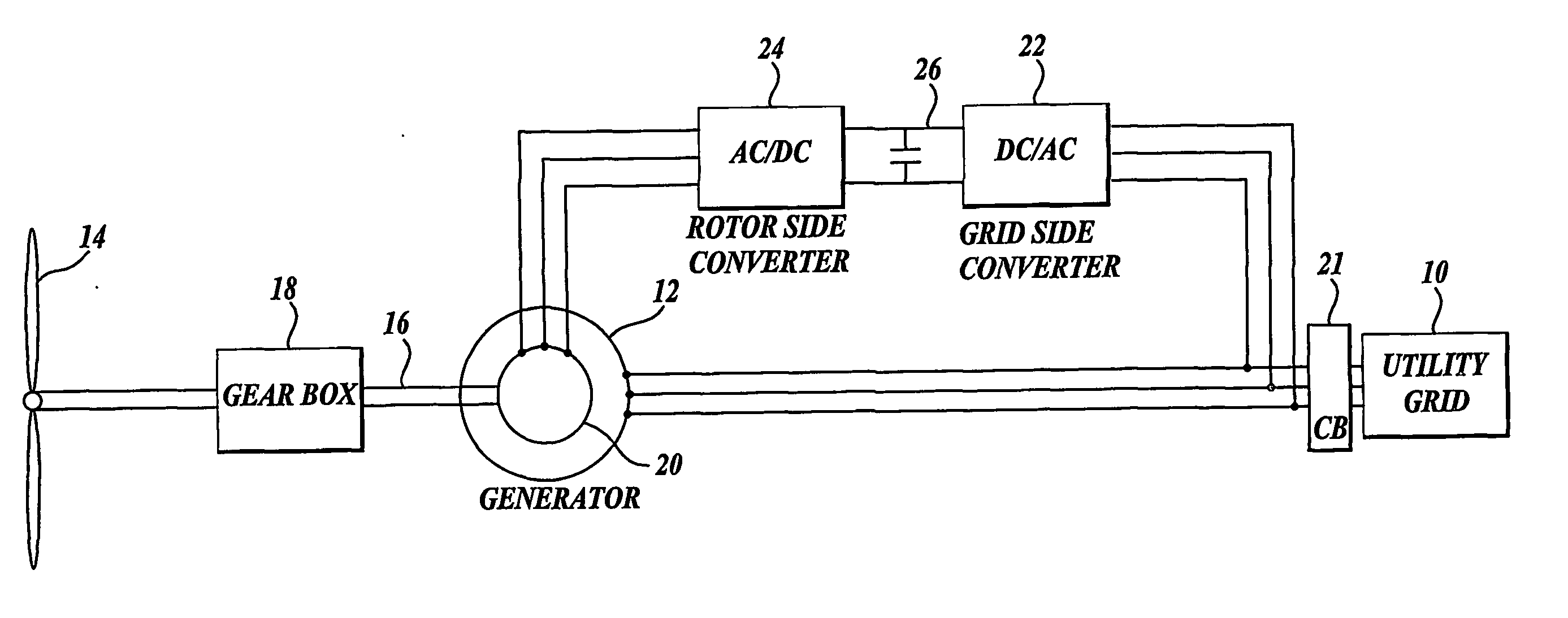
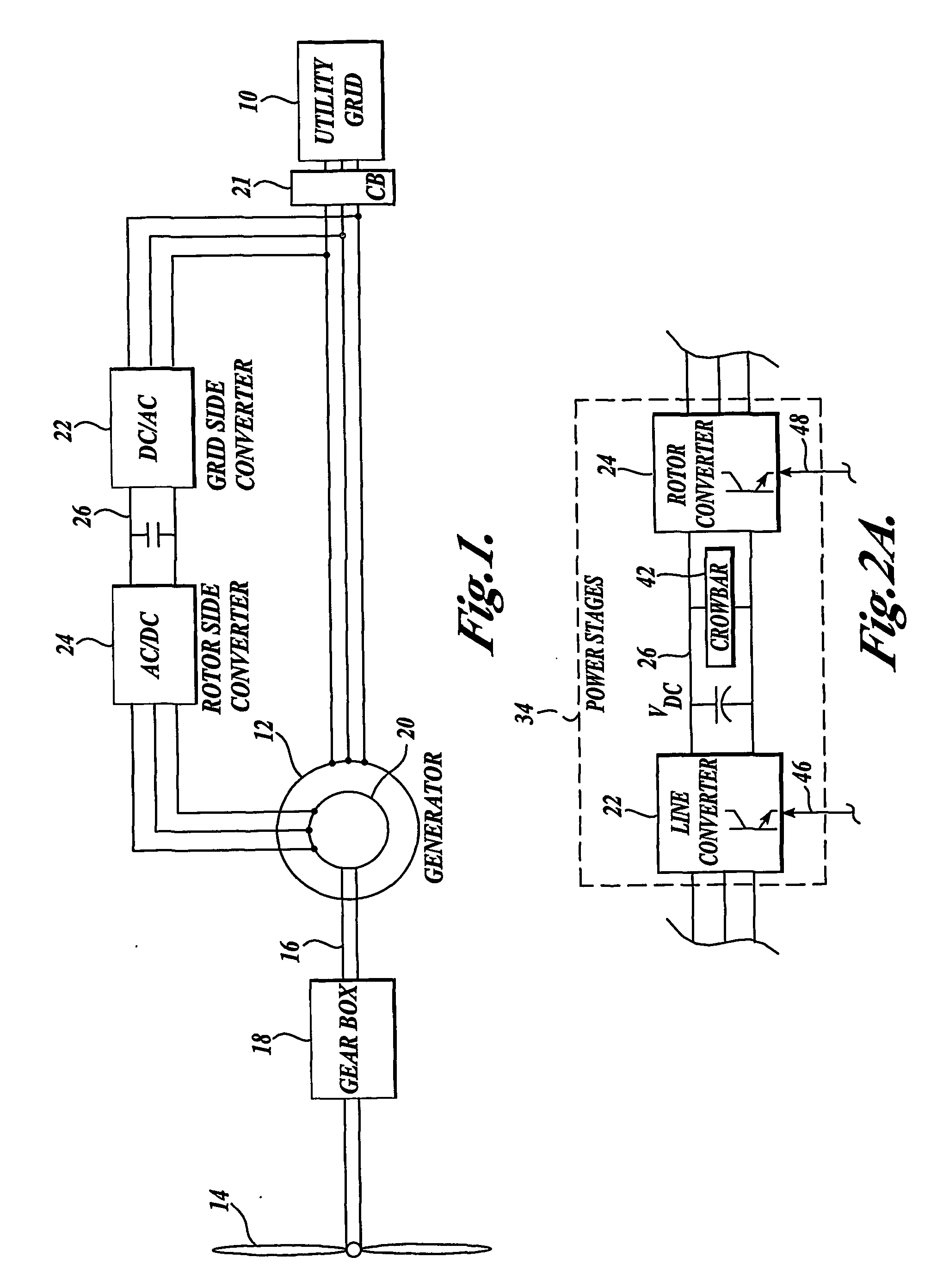
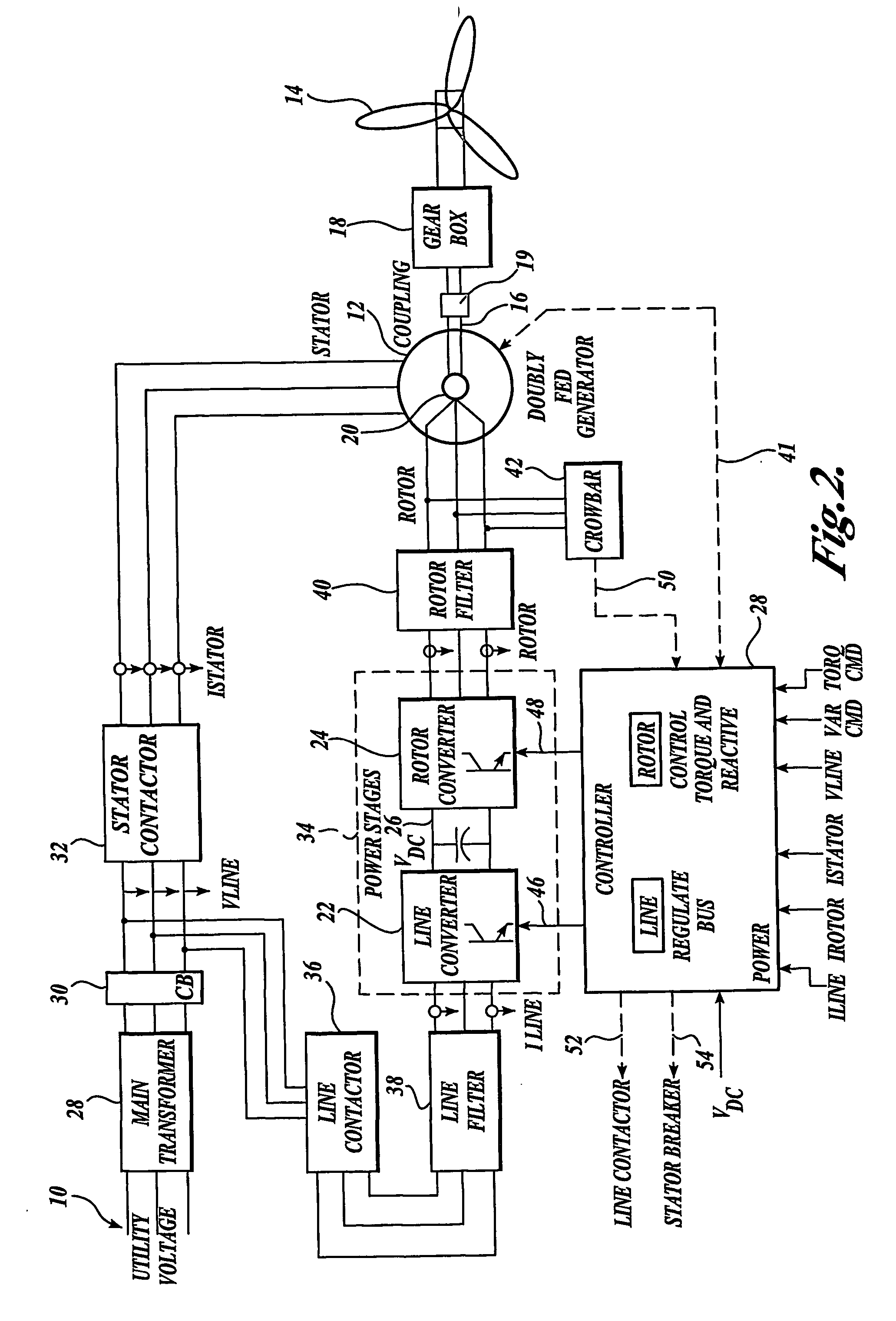
[0025] A simplified diagram of a doubly fed induction generator system is shown in FIG. 1. A utility grid 10 energizes the windings of the generator stator 12 (represented as the outer circle). Typically the grid supplies three phase alternating current. Supplied line voltage can be designated as VLine or VL and supplied line current designated as ILine or IL. The three phase parameters can be designated as: VLab, VLbc, VLca for phase to phase voltages; ILa, ILb, ILc for phase currents. The stator voltage can be designated Vs, stator current Is, and three phase parameters: Vsab, Vsbc, Vsca for phase to phase voltages; Isa, Isb, Isc for phase currents.

[0026] At the rotor side, the wind-driven blade assembly 14 drives the rotor shaft 16, such as through a gear box 18. This generates the mechanical force to turn the DFIG rotor 20 (represented as the inner circle). The rotor electrical connections are through slip rings. Rotor voltage can be represented as Vr, and ro...


PUM


Abstract

A controller (28) for a doubly fed induction generator (12,20) adjusts control signals to a rotor side converter (24) and line side converter (22) to adjust rotor current when a voltage transient on a utility grid (10) occurs, so that the doubly fed induction generator can ride through the transient. The controller can also turn off the transistors of the rotor side converter (24) to reduce rotor current and/or activate a crowbar (42) to reduce the voltage of the DC link (26) connecting the converters (22, 24) when significant voltage transients occur on the grid (10). This permits continued operation of the DFIG system without disconnecting from the grid.

Description

CROSS-REFERENCE TO RELATED APPLICATION [0001] This application claims the benefit of U.S. provisional Application No. 60 / 467,328, filed on May 2, 2003.FIELD OF THE INVENTION [0002] The present invention relates to power electronics converters used in variable speed machine control, particularly those used in wind turbines. More specifically, the present invention relates to a control system having power electronics converters for doubly fed induction generators to allow a variable speed turbine to continue to operate in the presence of voltage transients that occur on a utility grid. BACKGROUND OF THE INVENTION [0003] Large scale (Megawatt class) wind turbines are becoming increasingly used as a source of renewable energy for utilities throughout the world. One approach to achieving efficient conversion of the mechanical power from the blades of a wind turbine into electrical energy supplied to a utility grid is the use of a doubly fed induction generator (DFIG) combined with a powe...

Claims


Application Information

Patent Timeline
IPC IPC(8): F03D9/00H02P9/04H02P7/06H02P9/00H02P9/10H02P9/46H02P11/00
CPCF03D7/0272F03D9/003F05B2270/107F05B2270/337H02P2101/15H02P9/102H02P9/46Y02E10/723H02P27/05H02P9/007F03D9/255Y02E10/72
Inventor HUDSON, RAYMOND M.
Owner SCHNEIDER ELECTRIC SOLAR INVERTERS USA
Why Eureka
Try Eureka