Multiple magnet coil in gap generator

Inactive Publication Date: 2007-03-08
TELEDYNE SCI & IMAGING +1
View PDF8 Cites 45 Cited by
  • Summary
  • Abstract
  • Description
  • Claims
  • Application Information

AI Technical Summary

Benefits of technology

[0014] The major goal of the yoked spaced apart magnet array arrangement is to ensure that the coil passing through the magnet gap experiences maximum flux density with parallel flux lines running perpendicular to a diameter of the coil. The flux density and the parallel orientation of the flux lines can be further e

Problems solved by technology

However, the moving magnet generator may not alw

Method used


Image

  • Multiple magnet coil in gap generator
  • Multiple magnet coil in gap generator
  • Multiple magnet coil in gap generator

Examples


Embodiment Construction

[0043] The following description is provided to enable any person skilled in the art to make and use the invention and sets forth the best modes contemplated by the inventor of carrying out his invention. Various modifications, however, will remain readily apparent to those skilled in the art, since the general principles of the present invention have been defined herein specifically to provide an improved transducer system for generation of electric current.

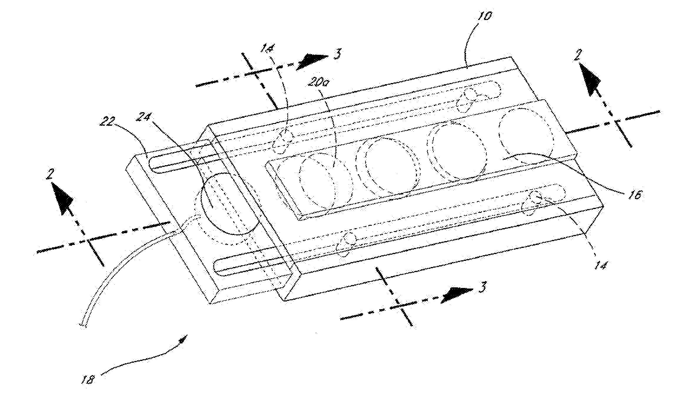
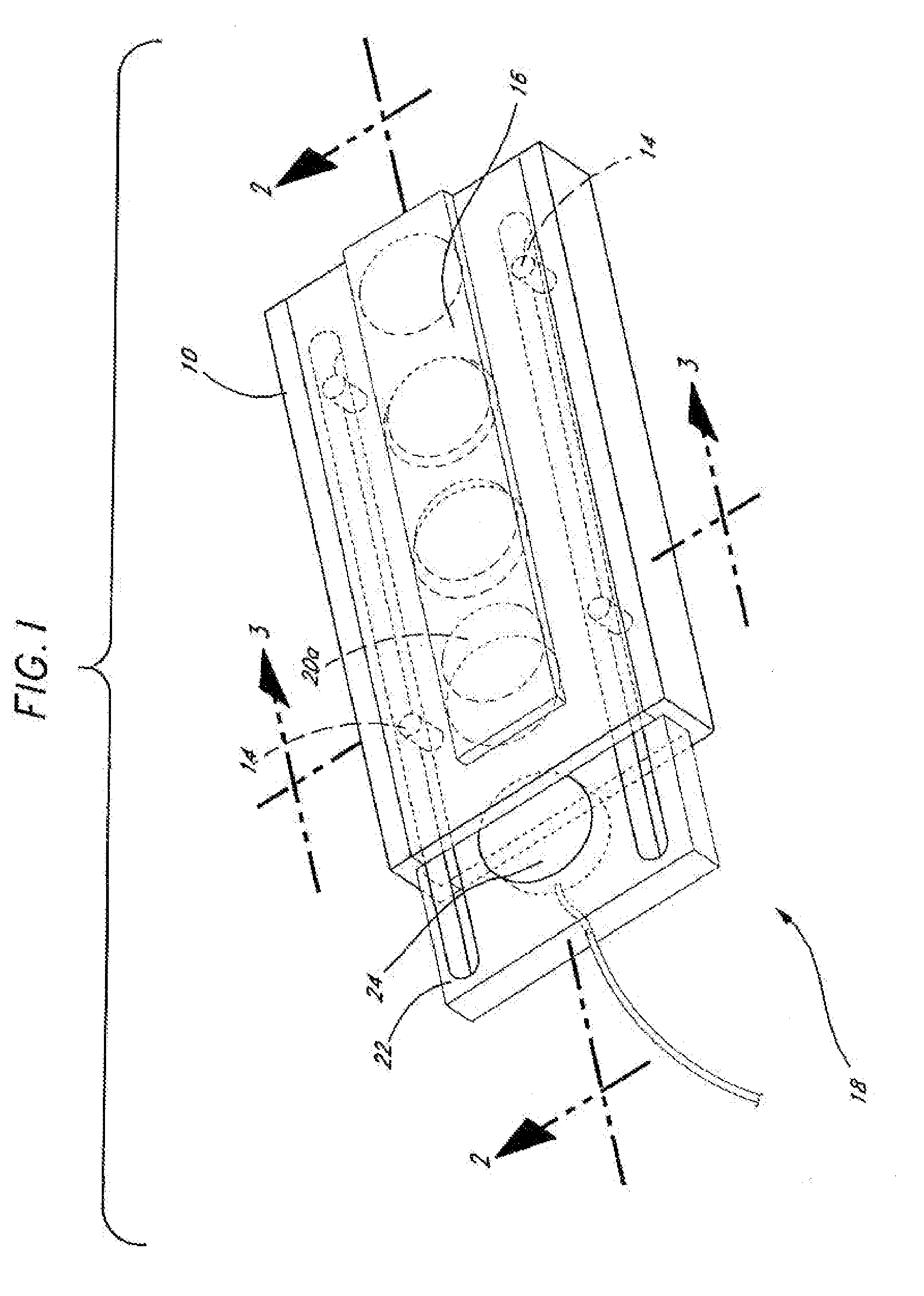
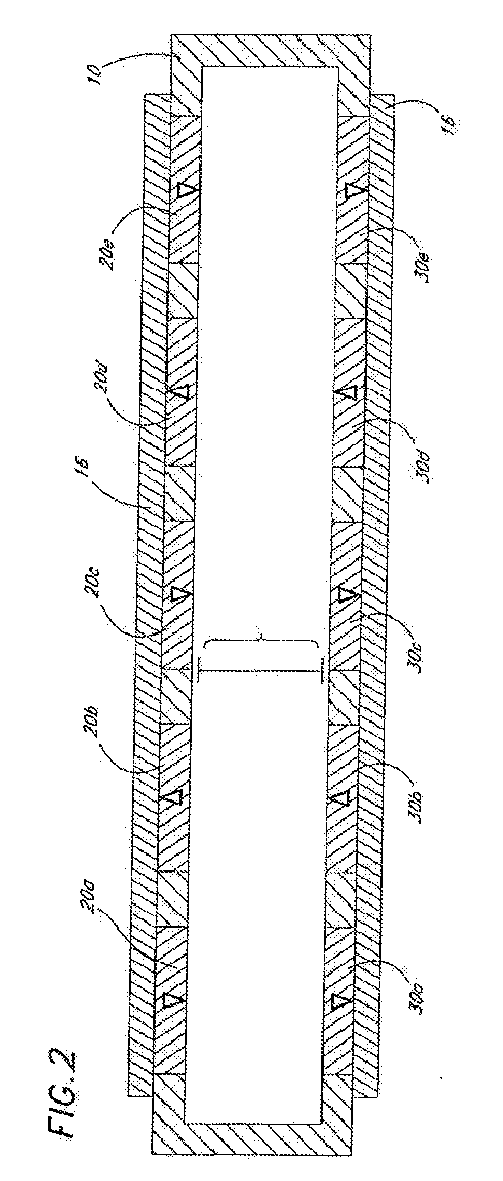
[0044] The inventor has continued to work on the problem of compact electrical generating systems and has now developed a variety of novel generator configurations wherein an unoptimized prototype is capable of generating better than 70 mW of power in response to reciprocal motion (e.g., a 2 cm motion at 5.5 Hz) of the type that is readily obtainable when a person wearing the generator simply walks. This is significantly more efficient than a moving magnet configuration even where the moving magnet configuration employs signifi...


PUM


Abstract

The present invention is an improved energy harvester or generator based on a yoked magnet array design based on a plurality of magnets arranged into at least two spaced apart linear or circular magnet arrays. The spaced apart magnet arrays are juxtaposed with each magnet in one array attractively interacting with the corresponding magnet in the other array across a small gap. The magnetic flux across the gap is further enhanced by having adjacent magnets in each array having alternate magnetic orientation and by providing a magnetic yoke of magnetically permeable material for the magnet ends of each array that do not face the gap. The gap is provided to allow a conductor in the form of a coil fit between the magnets. Relative motion between the coil and the magnets results in maximal generation of electrical power by the coil.

Description

CROSS-REFERENCE TO PRIOR U.S. APPLICATIONS [0001] The present application claim priority to Provisional U.S. Application 60 / 683,863 filed May 23, 2005, the content of which is incorporated here by reference.BACKGROUND OF THE INVENTION [0002] 1. Area of the Art [0003] The present application has to do with specialized generators for electric current by moving a conductor relative to a magnetic source. [0004] 2. Description of the Related Art [0005] The present inventor has had extensive experience in the art of magnetic transducers with power generation capability. The reader's attention is drawn to U.S. Pat. No. 6,768,230 (27 Jul. 2004), U.S. Pat. No. 6,798,090 (28 Sep. 2004), U.S. Pat. No. 6,809,427 (26 Oct. 2004), U.S. Pat. No. 6,812,598 (2 Nov. 2004), and U.S. Pat. No. 6,861,772 (1 Mar. 2005) which are hereby incorporated herein by reference. In those patents the present inventor disclosed a number of novel magnetic generation systems wherein one or more magnets were moved relati...

Claims


Application Information

Patent Timeline
IPC IPC(8): H02K41/00
CPCB82Y25/00H01F1/0045H01F1/14708H01F1/37H01F7/0221H02K41/0356H02K1/02H02K3/30H02K5/167H02K21/24H02K35/04H01F7/0289H02K41/00B82Y40/00
Inventor CHEUNG, JEFFREY T.TOMSIC, RICHARD RAYMOND
Owner TELEDYNE SCI & IMAGING
Why Eureka
Try Eureka