
Light-Emitting Device

a light-emitting device and panel technology, applied in the field of panel, can solve the problem of lowering the yield of the light-emitting device itself, and achieve the effect of suppressing uneven luminance and dropping the opening ratio

Inactive Publication Date: 2007-03-08
SEMICON ENERGY LAB CO LTD
View PDF56 Cites 39 Cited by
  • Summary
  • Abstract
  • Description
  • Claims
  • Application Information

AI Technical Summary

Benefits of technology

The present invention provides a light-emitting device with a reduced number of thin film transistors in each pixel to prevent a drop in opening ratio and suppress uneven luminance caused by fluctuation in threshold voltage of current controlling TFTs. By restricting the difference in emission luminance of pixels to a certain range, the invention can prevent uneven luminance from being visually recognized by an observer. The invention also provides a method for determining the optimal values of the ratio W / L of the channel width W to the channel length L to achieve the desired level of fluctuation ΔVth of the threshold voltage.

Problems solved by technology

Besides, if the number of TFTs provided in a pixel is increased, there is a fear that yield of the light-emitting device itself is lowered.

Method used


Image

  • Light-Emitting Device
  • Light-Emitting Device
  • Light-Emitting Device

Examples


embodiment 1

[0166] In this embodiment, an example in which the present invention is applied to an actual light-emitting device by using the above described expressions 8 and 11 will be described.

[0167] In this embodiment, a light-emitting device having a resolution of QVGA of 320×240 and a size of 4 inches will be exemplified.

[0168] A pixel size of the 4-inch QVGA light-emitting device is about 84 μm×252 μm. When an attempt to obtain definite luminance is made, the intensity of current flowing through an EL element per unit area is determined. In this embodiment, it is made 3 mA / cm−2 per unit area.

[0169] Thus, a drain current Id of a current controlling TFT included in each of pixels is expressed by the following expression 22.

[0170] [Expression 22]

[0171] The above expression indicates a value of the drain current Id of the current controlling TFT when the opening ratio of the light-emitting device is 100%. Actually, in almost all cases, the opening ratio of the light-emitting device is not...

embodiment 2

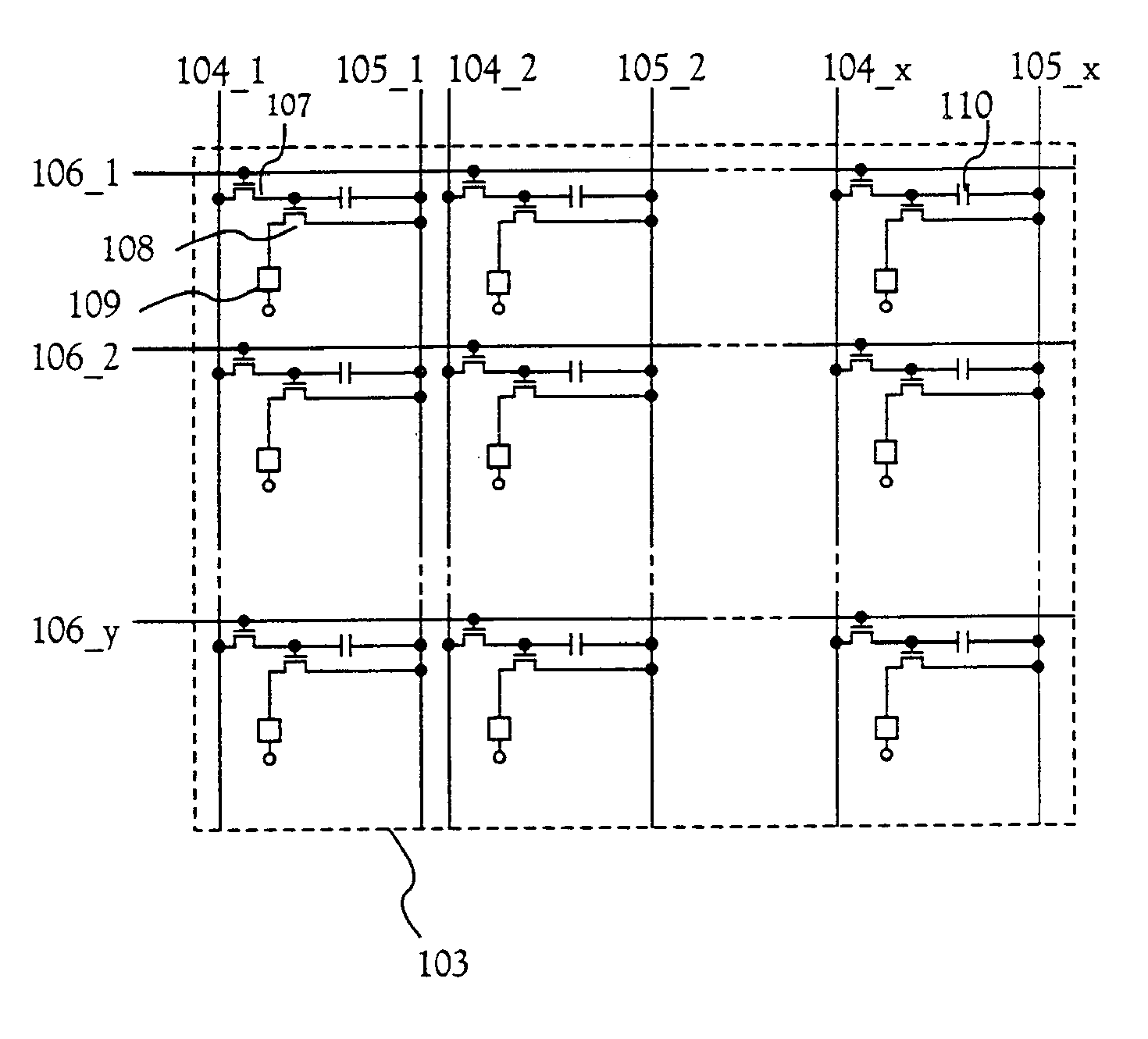
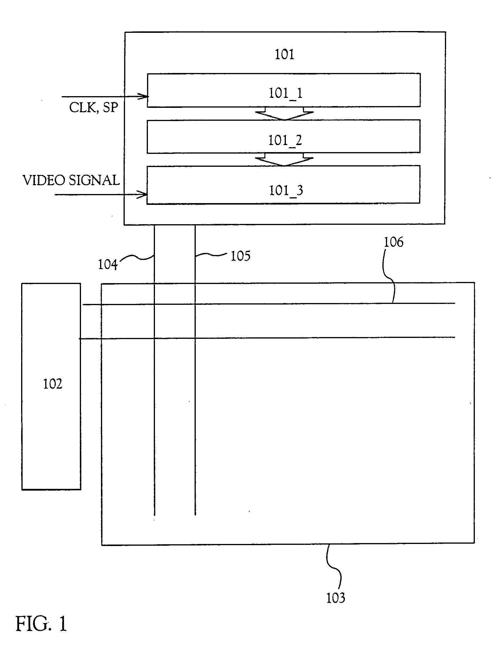
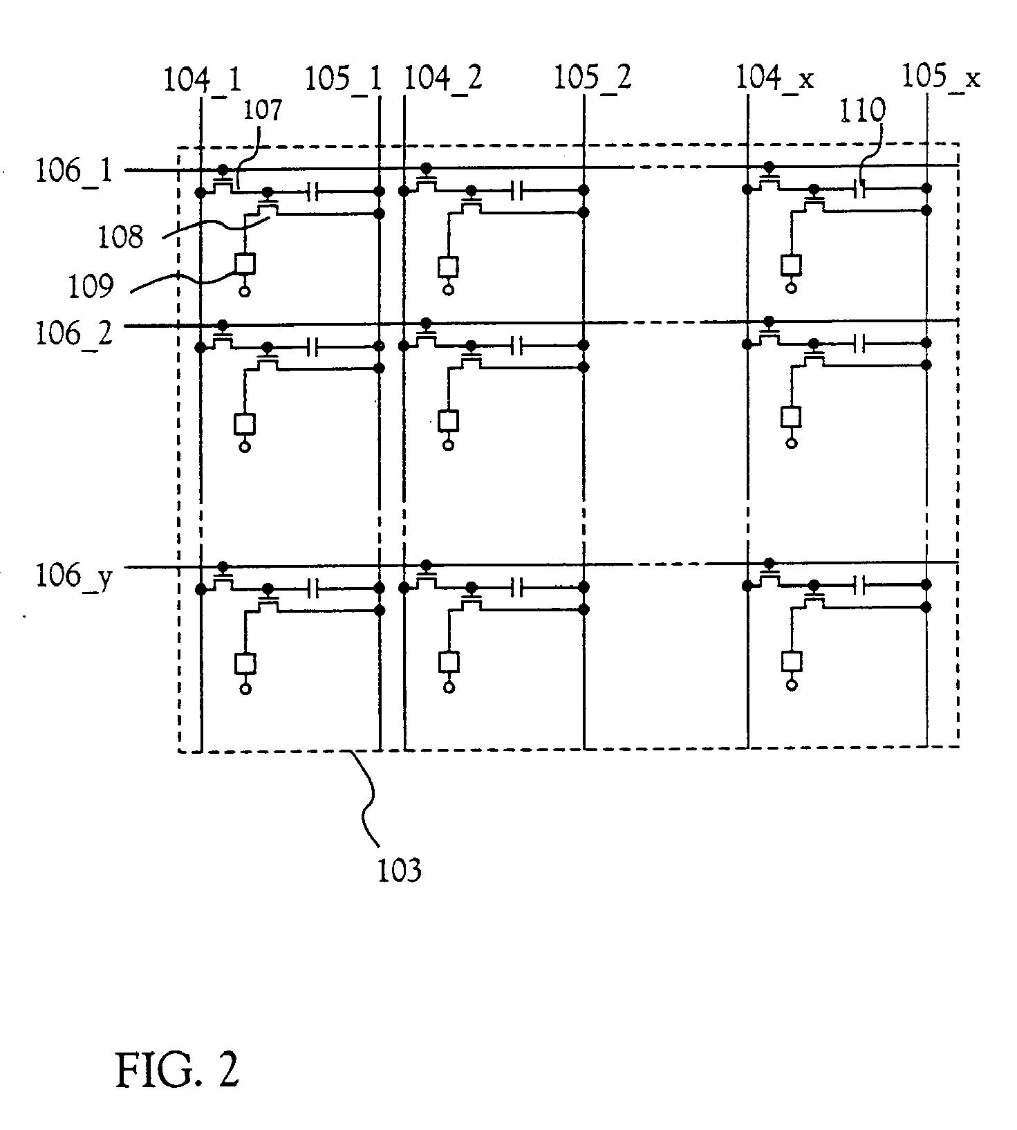
[0187] A driving method of a light-emitting device of the present invention will be described with reference to FIGS. 1 to 3.

[0188]FIG. 1 is a top view of a light-emitting device of the present invention. Reference numeral 101 designates a source signal line driving circuit; 102, a gate signal line driving circuit; and 103, a pixel portion. In this embodiment, although one source signal line driving circuit and one gate signal line driving circuit are provided, the present invention is not limited to this structure. Two source signal line driving circuits may be provided, or two gate signal line driving circuits may be provided.

[0189] The source signal line driving circuit 101 includes a shift register 101_1, a level shift 101_2, and a sampling circuit: 101_3. Note that the level shift 101_2 has only to be used as the need arises, and it may not be always used. Besides, although this embodiment is made to have such a structure that the level shift 101_2 is provided between the shi...

embodiment 3

[0206] In this embodiment, a detailed description will be given of a method of fabricating a pixel portion and TFTs (n-channel TFT and p-channel TFT) of a driving circuit provided on the periphery of the pixel portion on the same substrate at the same time.

[0207] First, as shown in FIG. 7A, an under film 701 made of an insulating film such as a silicon oxide film, a silicon nitride film, or a silicon nitride oxide film is formed on a substrate 700 made of glass such as barium borosilicate glass or alumino borosilicate glass, typified by #7059 glass or #1737 glass of Corning Inc. For example, a silicon nitride oxide film 701a fabricated from SiH4, NH3 and N2O by a plasma CVD method is formed to a thickness of 10 to 200 nm (preferably 50 to 100 nm), and a hydrogenated silicon nitride oxide film 701b similarly fabricated from SiH4 and N2O is formed to a thickness of 50 to 200 nm (preferably 100 to 150 nm) to form a laminate. In this embodiment, although the under film 701 is shown as ...


PUM


Abstract

There is provided an EL light-emitting device with less uneven brightness. When a drain current of a plurality of current controlling TFTs is Id, a mobility is μ, a gate capacitance per unit area is Co, a maximum gate voltage is Vgs(max), a channel width is W, a channel length is L, an average value of a threshold voltage is Vth, a deviation from the average value of the threshold voltage is ΔVth, and a difference in emission brightness of a plurality of EL elements is within a range of ±n %, a semiconductor display device is characterized in that A=2⁢Idμ*C0A(Vgs(max)-Vth)2≦WL≦(1+n100-1)2*AΔ⁢ ⁢Vth2Δ⁢ ⁢Vth≦(1+n100-1)*A*L / W

Description

BACKGROUND OF THE INVENTION [0001] 1. Field of the Invention [0002] The present invention relates to an EL panel in which an EL element formed on a substrate is sealed between the substrate and a cover member. Further, the present invention relates to an EL module in which an IC is mounted in the EL panel. Incidentally, in the present specification, the EL panel and the EL module are generally referred to as a light-emitting device. The present invention further relates to an electronic instrument using the light-emitting device. [0003] 2. Description of the Related Art [0004] In recent years, a technique for forming a TFT on a substrate has been greatly advanced, and application to an active matrix display device has been advanced. Especially, since a TFT using a polysilicon film has an electron field-effect mobility (also called mobility) higher than that of a TFT using a conventional amorphous silicon film, a high speed operation is possible. Thus, control of a pixel, which is co...

Claims


Application Information

Patent Timeline
Patent Type & Authority Applications(United States)
IPC IPC(8): G09G3/30H05B44/00G09F9/30G09G3/20G09G3/32H01L27/32H01L29/786H01L51/50H05B33/12H05B33/14
CPCG09G2300/0809H01L29/78621H01L51/5203H01L27/3262G09G2320/043G09G3/3275G09G2320/0233G09G2300/0819H01L29/42384H01L27/3211H01L27/32G09G2300/0814G09G2300/0861G09G3/3266G09G2300/0852G09G2300/0842H01L27/3244G09G2300/0417G09G3/3233G09G2300/0426H01L27/1296H01L29/78627H01L29/4908H01L29/7866H10K59/35H10K59/123H10K59/124H10K59/1213H10K59/8722H10K59/871H10K50/805H10K59/12H10K59/1216H10K59/00H10K59/1201H01L27/1214H01L29/78672H01L27/1222H01L27/1251H01L29/78654H01L29/78696
Inventor YAMAZAKI, SHUNPEIKOYAMA, JUNOSADA, MAI
Owner SEMICON ENERGY LAB CO LTD
Learn More