Piezoelectric Actuator, Ink-Jet Head, Method Of Producing Piezoelectric Actuator, And Method Of Producing Ink-Jet Head

a piezoelectric actuator and actuator technology, applied in the direction of piezoelectric/electrostrictive transducers, conductive pattern formation, transducer types, etc., can solve the problem that the substrate is exposed to a high-temperature environment during calcination, the piezoelectric characteristics cannot be achieved in some cases, and the exfoliation layer is removed. , to achieve the effect of reducing the degradation of piezoelectric characteristics, less thermal load, and simple process

Inactive Publication Date: 2007-03-08
BROTHER KOGYO KK
View PDF8 Cites 3 Cited by
  • Summary
  • Abstract
  • Description
  • Claims
  • Application Information

AI Technical Summary

Benefits of technology

[0009] The present invention is made in view of a situation described above, and an object of the present invention is to provide a piezoelectric actuator and an ink-jet head which are capable of suppressing the degradation of piezoelectric characteristics. Another object of the present invention is to provide a method of producing the piezoelectric actuator and a method of producing an ink-jet head with less thermal load and with a simple process.
[0012] According to the present invention, the piezoelectric layer is formed by using the aerosol deposition method (a method for forming a thin film by blowing aerosol containing particle material (particulate material) to a target object to deposit the material thereon) in which no calcination step is required; and a low-sintering temperature material, which starts to sinter at a temperature (sintering-start temperature) that is not more than the annealing temperature in the step of subjecting the piezoelectric layer to annealing treatment, is used as a conductive material for forming the electrode layer on the substrate. Accordingly, upon forming the first electrode layer and upon forming the piezoelectric layer, there is no need to perform the calcination under a severe condition. In addition, in the annealing step required after the formation of piezoelectric layer, the calcination of the first electrode layer formed of the low-sintering temperature material can be performed simultaneously. In other words, there is no need to perform the calcination of the first electrode layer separately. Accordingly, the thermal cycle during the producing process can be made as minimum as necessary, thereby suppressing the exfoliation of layers and diffusion of substrate material into the piezoelectric layer due to the thermal history. Thus, it is possible to lower the degradation of piezoelectric characteristics. Further, it is possible to simplify the producing process, thereby contributing to the energy conservation.
[0014] The method of the present invention may further include, before the annealing treatment step, a pre-calcination step of subjecting the first electrode layer to a pre-calcination at a temperature of not more than 420° C. In the pre-calcination, it is preferable that a temperature for pre-calcination is as low as possible to an extent at which the conductive material can be melted and the particles can be adhered to each other. Specifically, the temperature of pre-calcination may be not more than 420° C., for the purpose of suppressing the effect of thermal history as small as possible.
[0016] According to a second aspect of the present invention, there is provided a piezo electric actuator including a first electrode layer which is formed on a substrate and which includes metal-nano particles having a particle size of not more than 50 nm; a piezoelectric layer provided on the first electrode layer by blowing aerosol containing particles of a piezoelectric material onto the first electrode layer to deposit the particles on the first electrode layer; and a second electrode layer which is arranged on the piezoelectric layer and which pairs with the first electrode layer. This piezoelectric actuator includes the first electrode layer formed of the metal-nano particles having a particle size of not more than 50 nm and which is a low-sintering temperature material, and includes the piezoelectric layer formed by the aerosol deposition method. Accordingly, the piezoelectric actuator has satisfactory piezoelectric characteristics since the thermal loading in these layers are small during the producing process, and the diffusion of element from the substrate is suppressed.

Problems solved by technology

In the above-mentioned method, however, the substrate is exposed to a high-temperature environment during calcination.
Accordingly, due to a difference in a coefficient of thermal expansion of materials forming the layers respectively, a stress is generated in an interface of overlapping layers, which in turn causes exfoliation of the layers.
Therefore, sufficient piezoelectric characteristics cannot be achieved in some cases.

Method used


Image

  • Piezoelectric Actuator, Ink-Jet Head, Method Of Producing Piezoelectric Actuator, And Method Of Producing Ink-Jet Head
  • Piezoelectric Actuator, Ink-Jet Head, Method Of Producing Piezoelectric Actuator, And Method Of Producing Ink-Jet Head
  • Piezoelectric Actuator, Ink-Jet Head, Method Of Producing Piezoelectric Actuator, And Method Of Producing Ink-Jet Head

Examples


Embodiment Construction

[0024] An embodiment of the present invention will be described with reference to FIGS. 1 to 3.

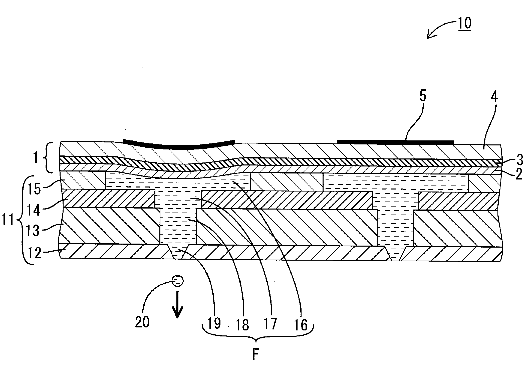
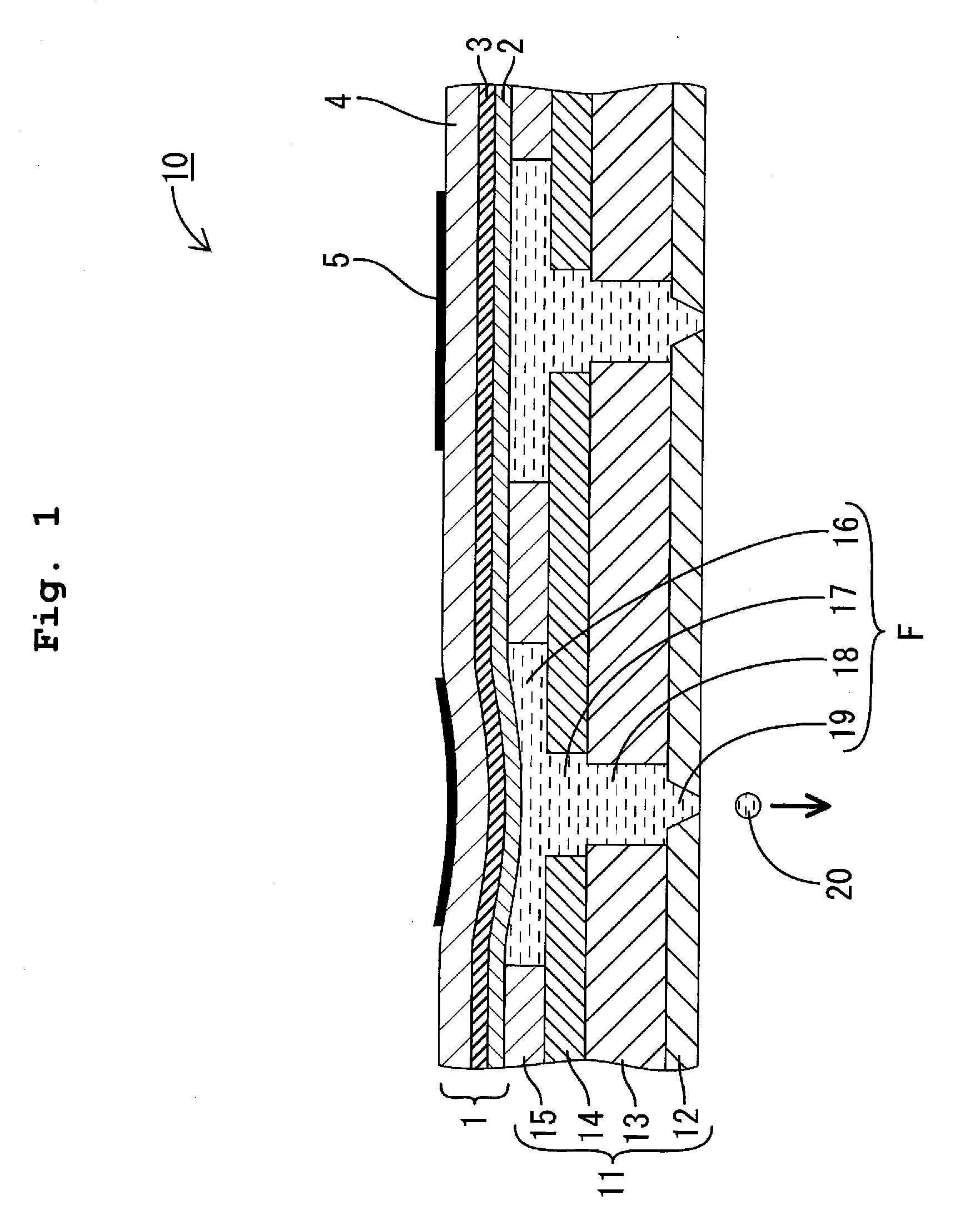
[0025]FIG. 1 shows an ink-jet head 10 of this embodiment. The ink-jet head 10 includes a channel unit 11(corresponding to the ink-channel forming body of the present invention) which has a plurality of pressure chambers 16 accommodating an ink 20 and an actuator plate 1 (corresponding to the piezoelectric actuator of the present invention) which is joined to the channel unit 11 so as to close the pressure chambers 16.

[0026] The channel unit 11 as a whole is in the form of a flat plate in which a nozzle plate 12, a manifold plate 13, a channel plate 14, and a pressure-chamber plate 15 are stacked in layers in sequence, and the channel unit 11 has a construction in which the plates 12, 13, 14, and 15 are joined to one another with an epoxy-based thermosetting adhesive.

[0027] The nozzle plate 12 is formed of a polyimide-based synthetic resin material, and a plurality of holes which are to ...


PUM

PropertyMeasurementUnit
temperatureaaaaaaaaaa
particle sizeaaaaaaaaaa
temperatureaaaaaaaaaa

Abstract

A method for a piezoelectric actuator and an ink-jet head uses, for forming a lower electrode on a vibration plate, metal-nano particles which can start to sinter with a low temperature as a conductive material; and uses, for forming a piezoelectric layer, an aerosol deposition method requiring no calcination step. Accordingly, upon forming the lower electrode and piezoelectric layer, any calcination under severe condition is not needed. In addition, the calcination of the lower electrode can be advanced simultaneously with an annealing step required after forming the piezoelectric layer. Accordingly, the thermal cycle during producing process can be minimized, thereby suppressing the exfoliation of layers and diffusion of material forming vibration plate into the piezoelectric layer due to thermal history, and consequently lower the degradation of piezoelectric characteristics.

Description

CROSS REFERENCE TO RELATED APPLICATION [0001] The present application is a Continuation-In-Part application of U.S. patent application Ser. No. 11 / 276,999 filed on Mar. 20, 2006, claiming priority from Japanese Patent Application No. 2005-082285, filed on Mar. 22, 2005, the disclosure of which is incorporated herein by reference in its entirety.BACKGROUND OF THE INVENTION [0002] 1. Field of the Invention [0003] The present invention relates to a piezoelectric actuator, an ink-jet head, a method of producing the piezoelectric actuator, and a method of producing the ink-jet head. [0004] 2. Description of the Related Art [0005] An example of a piezoelectric actuator used in an ink-jet head or the like is described in Japanese Patent Application Laid-open No. 11-334087. In this piezoelectric actuator, a substrate (vibration plate) is provided such that the substrate closes openings of pressure chambers each of which communicates with a nozzle opening in a channel forming body; and a low...

Claims


Application Information

Patent Timeline
Patent Type & Authority Applications(United States)
IPC IPC(8): B41J2/045
CPCB41J2/161B41J2/1623H01L41/0477Y10T29/49155H01L41/314Y10T29/42H01L41/0973H10N30/877H10N30/2047H10N30/074
Inventor YASUI, MOTOHIRO
Owner BROTHER KOGYO KK
Why Eureka
Try Eureka