System and method for evaluating a machined surface of a cast metal component

a technology of machined surface and cast metal, which is applied in the direction of television systems, instruments, and image enhancement, etc., can solve the problems of inability to reliably detect a pore with a concave region, the quality and reliability of such inspection is subject to the operator's overall capability and performance, and the system is not robust in a manufacturing production environment, so as to reduce the evaluation time of parts, improve product reliability, and reliably identify and detect surface defects

Inactive Publication Date: 2007-03-08
GM GLOBAL TECH OPERATIONS LLC
View PDF11 Cites 18 Cited by
  • Summary
  • Abstract
  • Description
  • Claims
  • Application Information

AI Technical Summary

Benefits of technology

[0006] In accordance with the present invention, a method and system provides a computer-based visual, non-contact, inspection of machined surfaces of cast metal parts, to reliably identify and detect surface defects, according to predetermined quality specifications. The disclosed method and system operates at production line rates. The method and system provide a vision-based system to identify and evaluate specific casting defects generally known as pores, and eliminate a need for close operator attendance and interaction that previously has been r

Problems solved by technology

Such voids are caused, for example, by impurities in the cast metal, and metal flow problems during the casting process.
The quality and reliability of such inspection is subject to the operator's overall capability and performance over time.
Such a system is not robust in a manufacturing production environment because of limitations related to identification of surface defects with edge-connected pores.
These limitations included an inability to reliably detect a pore with a concave region, a convex hull created prior to pore separation,

Method used


Image

  • System and method for evaluating a machined surface of a cast metal component
  • System and method for evaluating a machined surface of a cast metal component
  • System and method for evaluating a machined surface of a cast metal component

Examples


Embodiment Construction

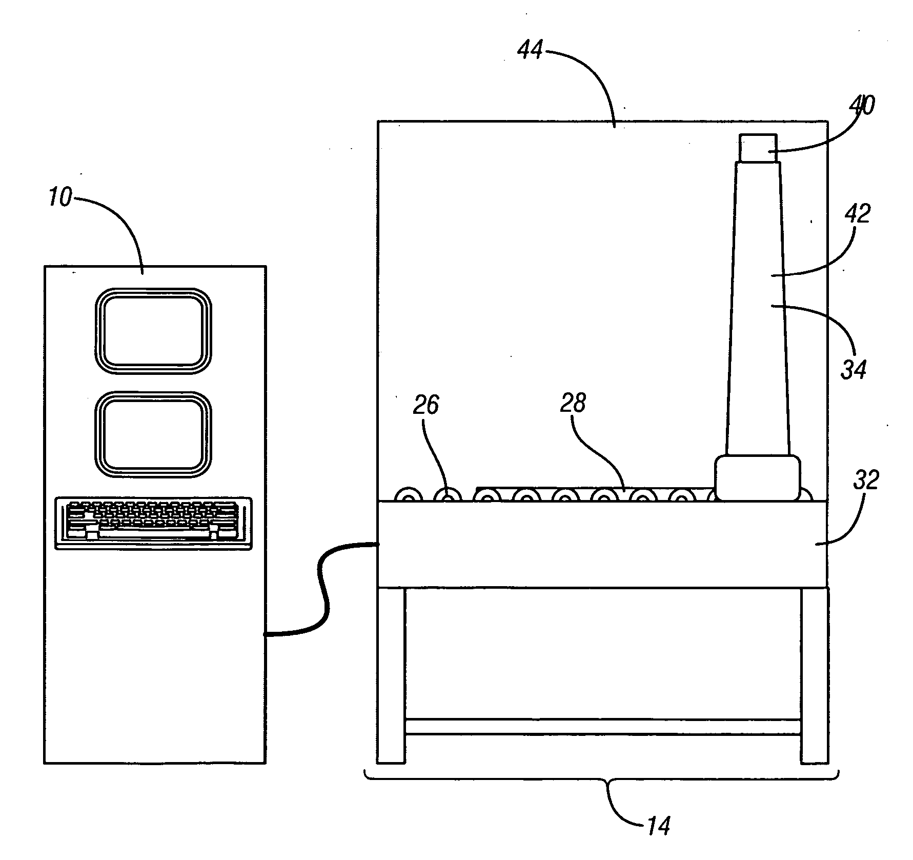
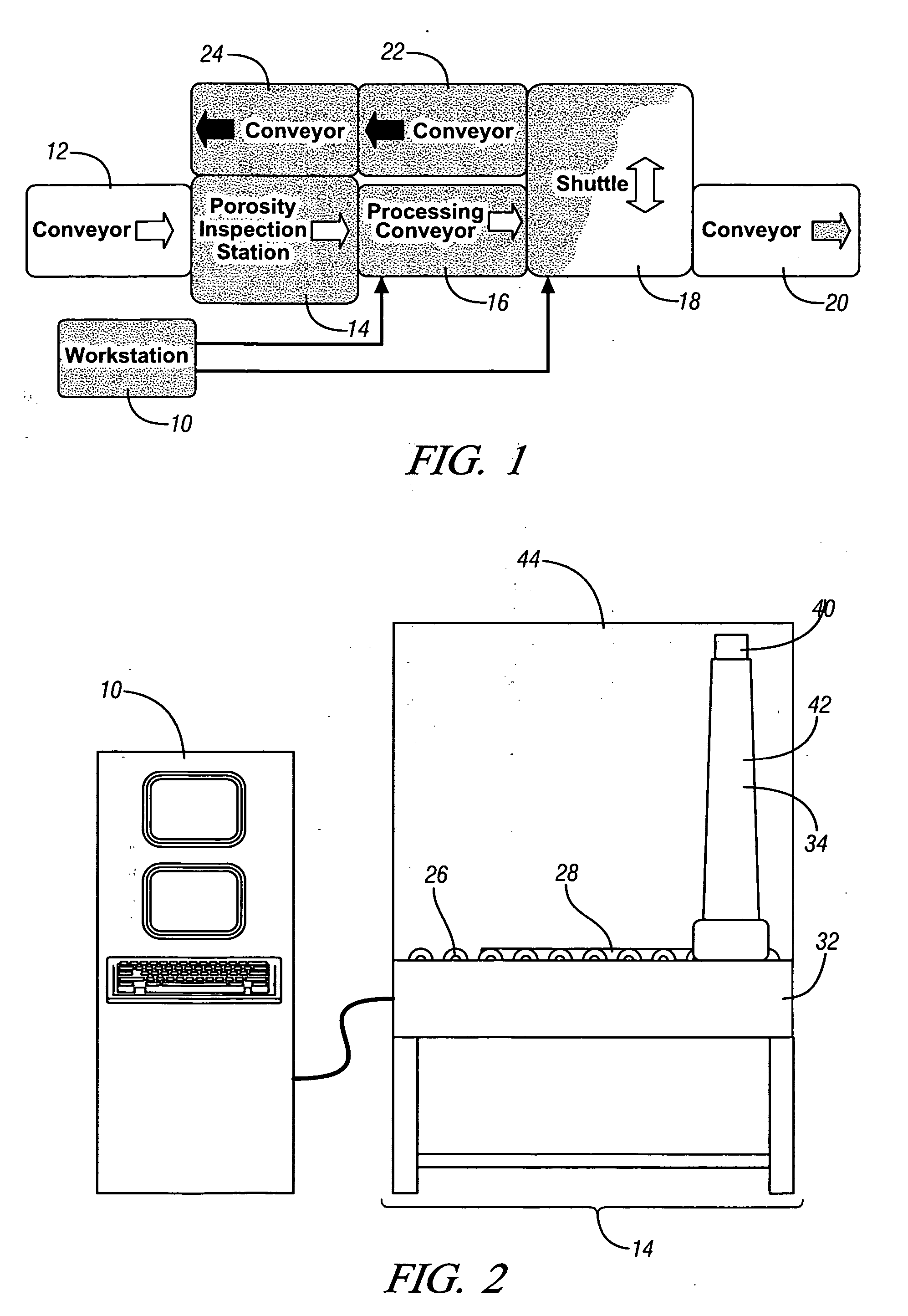
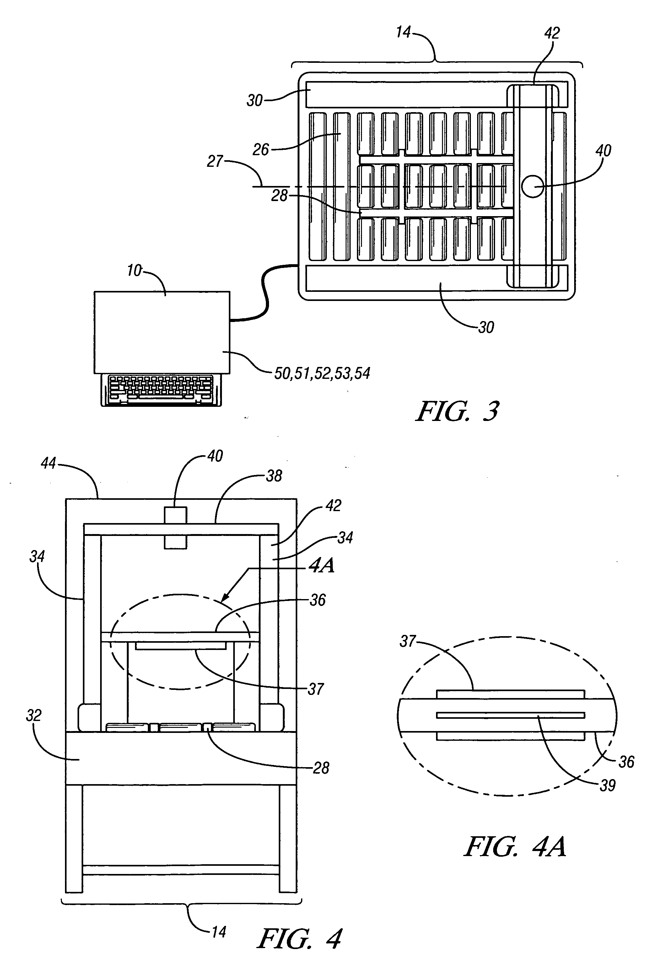
[0022] Referring now to the drawings, wherein the showings are for the purpose of illustrating the invention only and not for the purpose of limiting the same, FIG. 1 shows a schematic diagram of an exemplary vision system which has been constructed in accordance with an embodiment of the present invention. The exemplary vision system comprises a feed conveyor 12, porosity inspection station 14, processing conveyor 16, part shuttle 18, production conveyor 20, and scrap conveyors 22, 24. Each of the aforementioned devices is operably controlled by the workstation 10, as described in detail hereinafter. In overall operation, a component 1 for inspection (not shown) is presented to the feed conveyor 12, preferably at a production line rate. An exemplary line rate is preferably in the range of twenty seconds per component evaluated, whereas the actual process of acquiring an image of the surface of the component 1 takes approximately five to seven seconds. When the porosity inspection s...


PUM


Abstract

A method and system are provided for non-contact evaluation of a machined surface of a cast-metal part, including a vision-based porosity inspection station. A digital image of the machined surface is acquired, oriented and scaled to an XY coordinate system, filtered, and inverted. A second image is generated with known design surface features eliminated. Each pixel of the inverted digital image is XOR-compared with a corresponding pixel of the second image. Identified common surface features common to both images is analyzed statistically for conformance to a threshold. A defect is identified as any identified surface feature common to both images which exceeds the threshold. The system moves the part for further processing if a statistical analysis of defects indicates an acceptable component, and alternatively, removes the part from further processing if the analysis indicates a flawed component.

Description

TECHNICAL FIELD [0001] This invention pertains generally to cast-metal parts and vision-based, non-contact inspection systems for inspecting cast-metal parts. BACKGROUND OF THE INVENTION [0002] Manufacturers of cast-metal components having machined surfaces typically inspect each component to identify presence of surface defects, to determine if the component is in compliance with quality standards. Surface defects of interest typically include pores, or openings, which indicate voids in the cast metal. Such voids are caused, for example, by impurities in the cast metal, and metal flow problems during the casting process. A specific pore may indicate a small void, or it may indicate and lead to a much larger void below the surface. A pore may be located in a critical location in the cast part, such as an edge of a casting, or near a heat-affected zone, and affect overall part quality and performance in-use. Alternatively, a pore may be located in a non-critical location, with little...

Claims


Application Information

Patent Timeline
IPC IPC(8): H04N7/18H04N9/47
CPCG01N15/088G01N2015/0846G06T2207/30164G06T7/0091G06T2207/30136G06T7/0006G06T7/155
Inventor SWANGER, MICHAEL E.AGAPIOU, JOHN S.HOGARTH, ROBERT J.
Owner GM GLOBAL TECH OPERATIONS LLC
Why Eureka
Try Eureka