Fuel cell system and method of controlling electrical energy discharged in the fuel cell system

a fuel cell and electrical energy technology, applied in the field of fuel cell systems, can solve the problems of disadvantageous switching losses in converters such as dc/dc converters and downverters, water clogging may occur, and charge/discharge losses in energy storag

Active Publication Date: 2007-03-08
HONDA MOTOR CO LTD
View PDF1 Cites 12 Cited by
  • Summary
  • Abstract
  • Description
  • Claims
  • Application Information

AI Technical Summary

Benefits of technology

[0013] The present invention has been made taking the problems into consideration, and an object of the present invention is to provide a fuel cell system and a method of controlling discharge elec

Problems solved by technology

If water at the cathode becomes excessive, water clogging may occur.
At this time, charge/discharge losses in the energy storage, and switching losses in the converters such as the DC/DC converter and the downverter occur disadvantageously.
However, at the time of the discharge process (charge process for the energy storage), charge losses in the energy storage and DC/DC converter losses P9 occur.
As desc

Method used


Image

  • Fuel cell system and method of controlling electrical energy discharged in the fuel cell system
  • Fuel cell system and method of controlling electrical energy discharged in the fuel cell system
  • Fuel cell system and method of controlling electrical energy discharged in the fuel cell system

Examples


first embodiment

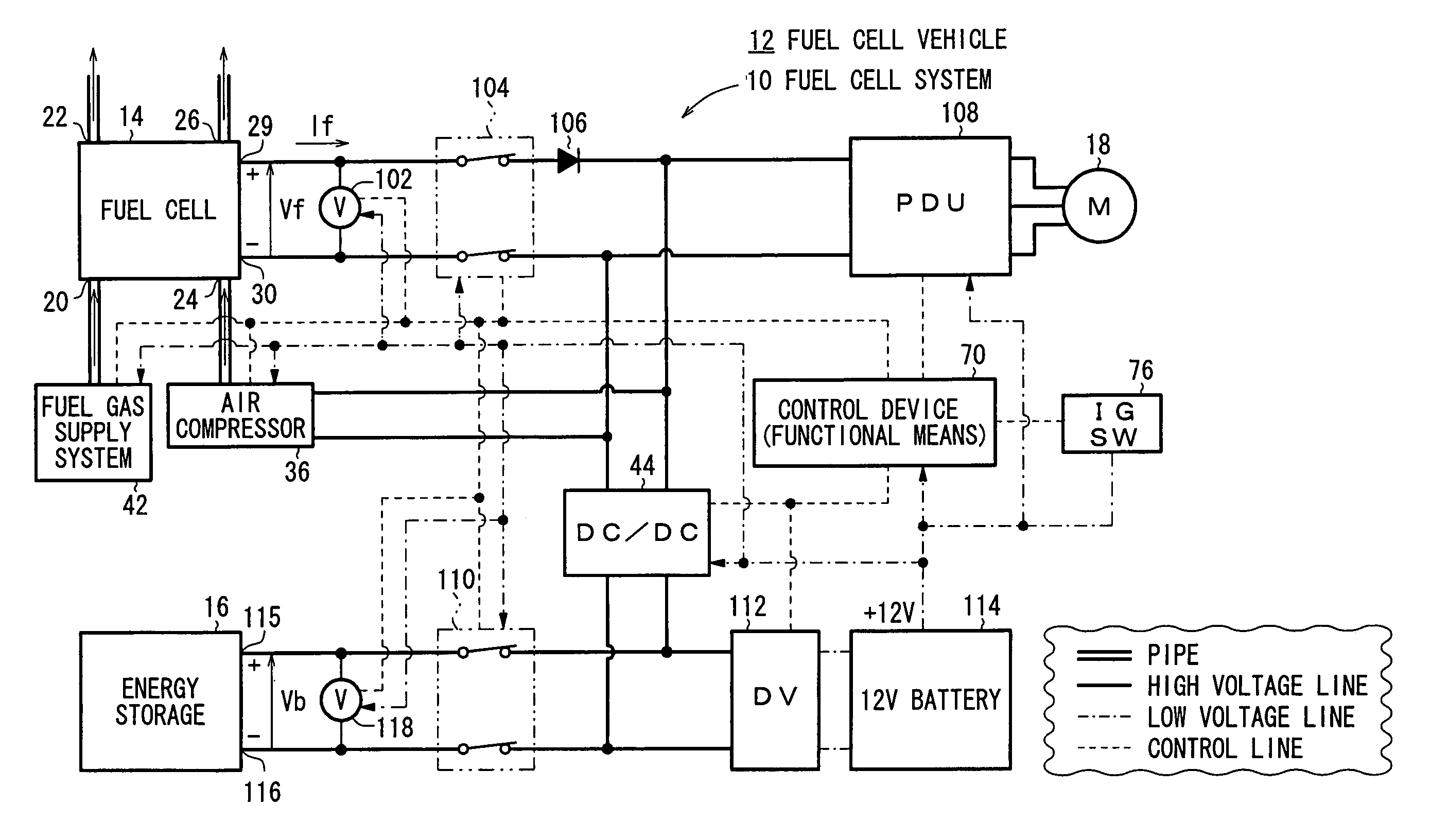
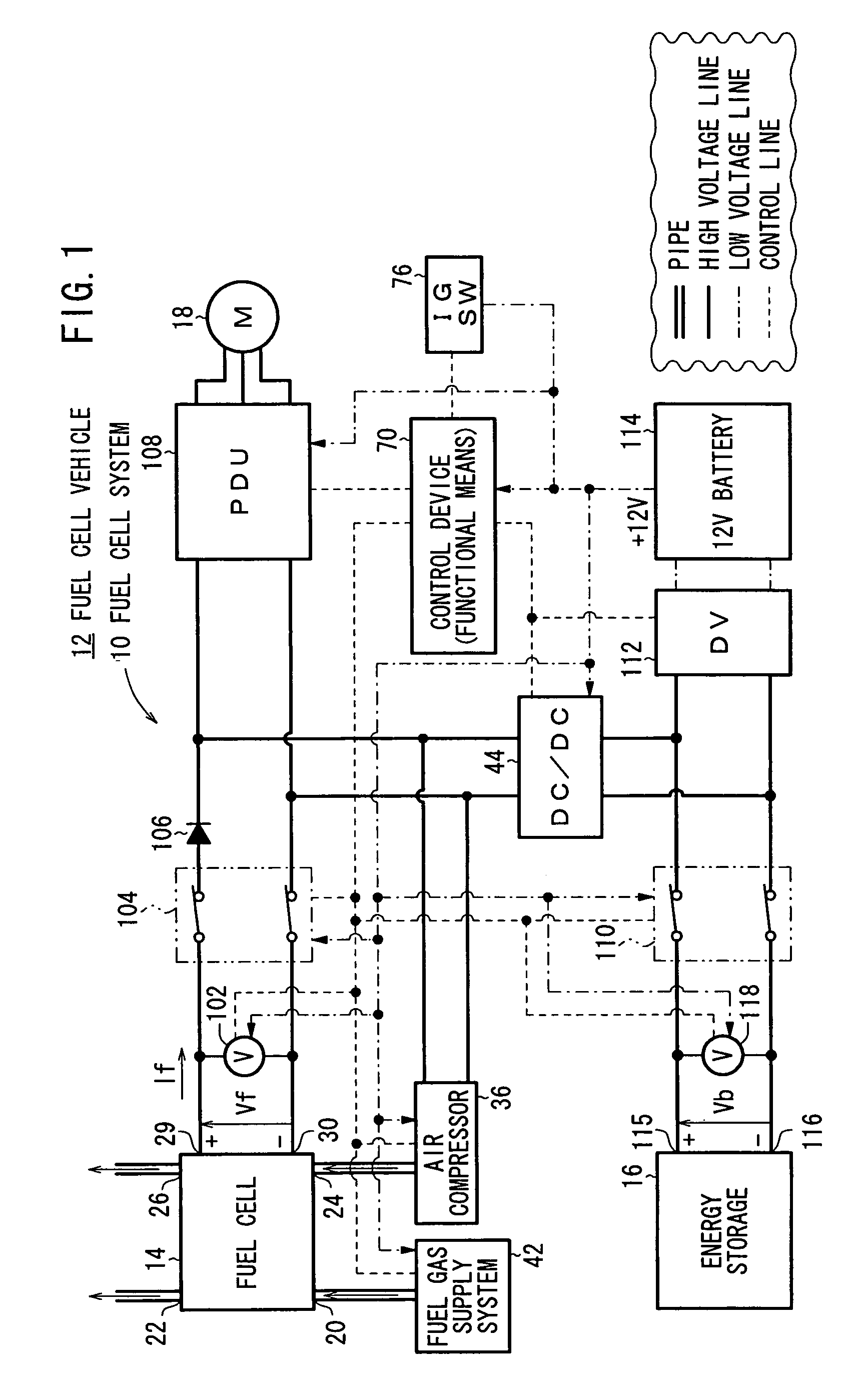
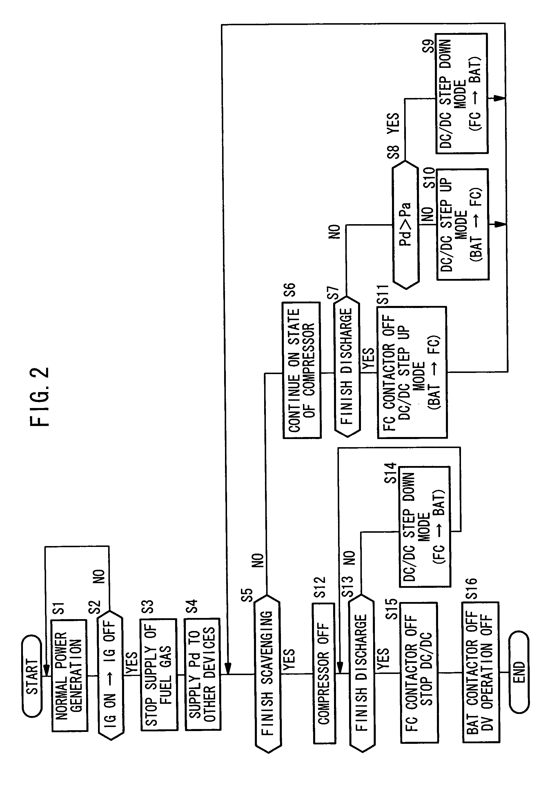
[0060] Basic structure and operation of the fuel cell system 10 and the fuel cell vehicle 12 equipped with the fuel cell system 10 have been described above. Next, specific operation of the fuel cell system 10 and the fuel cell vehicle 12 at the time of stopping operation will be described with reference to a flow chart of FIG. 2 (program executed by the control device 70) and a time chart of FIG. 3.

[0061] In step S1, the above described normal power generation of the fuel cell 14 is performed. In step S2, it is determined whether the ignition switch 76 has been switched from the ON state to the OFF state.

[0062] In the determination of step S2, when it is confirmed that the ignition switch 76 is switched from the ON state to the OFF state (time t10), in step S3, the supply of the fuel gas from the fuel gas supply system 42 to the fuel cell 14 is stopped.

[0063] At the same time, in step S4, the control of electrical energy (discharge electrical energy) Pd discharged from the fuel ...

second embodiment

[0081] In practice, the fuel cell vehicle 12 may have structure of a fuel cell vehicle 12A as shown in FIG. 4 according to a In the fuel cell vehicle 12A, in addition to the air compressor 36 and the DC / DC converter 44, a resistor 120 for discharging electrical energy of a PDU capacitor (not shown) is connected in parallel as a load between the high voltage lines.

[0082] In the second embodiment, as shown in FIG. 5, the operation of step S8 in FIG. 2 is replaced with operation of step S8a.

[0083] Further, compared with the time chart shown in FIG. 3, a time chart shown in FIG. 6 includes a waveform of the resistor consumption electrical energy Pr is added between the waveform of the +12V consumption electrical energy and the waveform of the energy storage charge / discharge electrical energy, and the waveform of the energy storage charge / discharge electrical energy is shifted to the discharge side between the time t10 and the time t12, by the amount corresponding to the resistor consu...

third embodiment

[0086] Next, FIGS. 7 and 8 show a flow chart and a time chart according to the present invention applied to the fuel cell vehicle 12A having the load of the resistor 120 in FIG. 4.

[0087] In the third embodiment, in the fuel cell vehicle 12A shown in FIG. 4, during the discharge process, in step S21, if the terminal voltage Vf of the fuel cell 14 becomes lower than the terminal voltage Vb of the energy storage 16 (see the time t12 in FIG. 8), in step S24, the BAT contactor 110 is placed into the OFF state (see the time t12 in FIG. 8), and in step S23, if the discharge process has not been finished, in step S22, the DC / DC converter 44 is placed into the step down mode, and the discharge electrical energy Pd is consumed through the DV 112 and the 12V battery 114, and the discharge electrical energy Pd is consumed by the resistor 120 to continue the discharge process.

[0088] When the terminal voltage Vf of the fuel cell 14 becomes a predetermined low voltage which is lower than the term...


PUM


Abstract

When a control device detects a request for stopping power generation of a fuel cell, electrical energy discharged from the fuel cell is supplied to an energy storage and other electrical devices such as an air compressor. At this time, electrical energy is supplied preferentially to the other electrical devices. Accordingly, discharge/charge losses in the energy storage can be reduced, compared to a technique in which an energy storage is charged preferentially at the time of stopping power generation of a fuel cell.

Description

BACKGROUND OF THE INVENTION [0001] 1. Field of the Invention [0002] The present invention relates to a fuel cell system in which electrical energy of a fuel cell is discharged when power generation in the fuel cell system is stopped, and relates to a method of controlling discharge electrical energy in the fuel cell system. [0003] 2. Description of the Related Art [0004] For example, a polymer electrolyte fuel cell employs a membrane electrode assembly which includes an anode (fuel electrode), a cathode (air electrode), and a polymer electrolyte membrane interposed between the electrodes. The electrolyte membrane is an ion exchange membrane. The membrane electrode assembly is sandwiched between a pair of separators. A fuel gas flow field is formed between the anode and one of the separators, and an oxygen-containing gas flow field is formed between the cathode and the other of the separators. In use, normally, a predetermined numbers of the membrane electrode assemblies and separato...

Claims


Application Information

Patent Timeline
IPC IPC(8): H01M8/04
CPCH01M8/0441H01M8/04559H01M8/04567H01M8/04753H01M8/0494H01M8/04947Y02T90/32H01M16/006H01M2250/20H01M2250/402Y02E60/50Y02B90/12H01M8/04955Y02B90/10Y02E60/10Y02T90/40
Inventor OJIMA, KUNIAKISAEKI, HIBIKI
Owner HONDA MOTOR CO LTD
Why Eureka
Try Eureka