Method and device for controlling the transition in a direct injection internal combustion engine

a technology of internal combustion engine and transition device, which is applied in the direction of electric control, machines/engines, instruments, etc., can solve the problems of irregular running of the internal combustion engine, inability to accept large amounts, and generally occurring step-change torques

Active Publication Date: 2007-03-08
VITESCO TECH GERMANY GMBH
View PDF3 Cites 19 Cited by
  • Summary
  • Abstract
  • Description
  • Claims
  • Application Information

AI Technical Summary

Benefits of technology

[0006] In the case of the method in accordance with the invention or the device for controlling the transition between two modes of operation, as applicable, with the characterizing features of the accompanying claims, there is the advantage that even a large step-change in the torque can still be successfully reduced, without detriment to the combustion of the fuel-air mixture. This is achieved by split injection, by which at least a portion of the fuel which is to be injected is injected into the cylinder or cylinders of the internal combustion engine during the compression phase. Injection during the compression phase results in three main effects which support a reduction in the torque: The reduced internal cooling in the cylinder results in a reduction in the mass of the air inducted, because a portion of the fuel load injected is injected at a point in time when the cylinder's valve is already closed (compression phase). In addition, there is the advantage that the combustion is made more inefficient, because when the injected fuel is injected late the swirling is less marked. Finally, measurements have also shown it is advantageous in that the smoothness of running of the internal combustion engine is unchanged if the ignition angle is retarded even more with injection during the compression phase. By retarding the ignition angle, a further reduction in the torque can be achieved. It is seen as particularly advantageous that the invention achieves a significantly greater reduction of the step-change in the torque without detriment to the smoothness of running of the internal combustion engine.
[0010] It is also seen as a good solution if, after the switchover, normal operation of the standard injection for the mode of operation concerned is resumed as soon as torque smoothing is completed. For example, if a switchover has been made to operation with a small valve lift it is then possible to set the control of the air mass, the fuel load and the ignition angle to the values specific to this mode of operation. This has no negative effect on the smoothness of running of the internal combustion engine, so that this switchover operation is imperceptible even to the occupants of the vehicle.
[0012] It is further advantageous, when switching over to operation with a small valve lift, to first open the throttle valve, to retard the ignition angle back to a permissible minimum value and, if necessary, to activate split injection in the compression phase. This is the most reliable way of compensating for a step-change in torque.

Problems solved by technology

It is already known that a step-change in torque generally occurs when switching over between two modes of operation, and that depending on the mode of operation this can be impermissibly large.
The step-change in torque can lead to irregular running of the internal combustion engine, which makes itself evident in driving use in undesirable ways, for example as juddering.
However, the late combustion of the fuel-air mixture effects a reduction in the torque.
With a large step-change in the air mass, the situation could arise in which a resetting of the ignition angle alone is no longer sufficient to compensate for the step-change in torque.
The price for this is a correspondingly higher fuel consumption.

Method used


Image

  • Method and device for controlling the transition in a direct injection internal combustion engine
  • Method and device for controlling the transition in a direct injection internal combustion engine
  • Method and device for controlling the transition in a direct injection internal combustion engine

Examples


Embodiment Construction

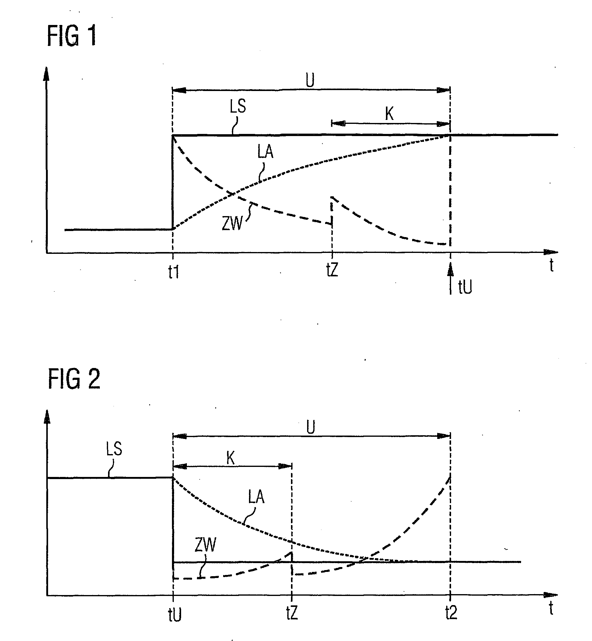
[0020] The way in which the switchover between two modes of operation functions will be explained in more detail for an exemplary embodiment in accordance with the invention, as shown in FIG. 1, by reference to a diagram. By way of example, it is assumed that an internal combustion engine operated using fuel direct injection is to be switched over from operation with a large valve lift on the inlet and / or the exhaust valves to operation with a small valve lift. On the one hand this switchover will result in the torque generated being less, and on the other hand this mode of operation is more fuel-saving, so that under certain operating conditions, for example under partial load when the maximum torque is not demanded of the engine, a fuel-saving mode of operation with the small valve lift appears advantageous. As a result of the switchover to operation with a small valve lift, it is no longer possible for as much air to flow into the cylinders of the internal combustion engine as be...


PUM


Abstract

During the changeover from a first operating mode of a spark-ignition engine with direct fuel injection to a second operating mode, in particular between a homogeneous stoichiometric and homogeneous lean, stratified or HCCI operation with changeovers of the valve stroke or the valve phase, there is the risk of an undesired torque jump, which can lead to a perceptible jolting of the vehicle or to a disturbance in the running of the spark-ignition engine. The invention thus proposes, in particular in the case of an inadmissibly large torque jump, the initiation of a multiple injection of fuel in addition to the conventional compensation by the displacement of the ignition angle. A partial quantity of said fuel is injected during the compression phase to reduce the degree of efficiency, thus reducing the torque produced.

Description

CROSS REFERENCE TO RELATED APPLICATIONS [0001] This application is the US National Stage of International Application No. PCT / EP2004 / 052023, filed Sep. 3, 2004 and claims the benefit thereof. The International Application claims the benefits of German application No. 10341070.8 filed Sep. 5, 2003. All applications are incorporated by reference herein in their entirety.FIELD OF THE INVENTION [0002] The invention concerns a method or a device, as applicable, in accordance with the accompanying claims, by which it is possible to control the transition from a first mode of operation of an internal combustion engine operating with direct injection of the fuel to a second mode of operation, for example between a homogeneous stoichiometric and a homogeneous lean stratified or HCCI mode (homogeneous charged compression ignition), switchovers of the valve lift or the valve phase. BACKGROUND OF THE INVENTION [0003] It is already known that a step-change in torque generally occurs when switchi...

Claims


Application Information

Patent Timeline
Patent Type & Authority Applications(United States)
IPC IPC(8): G06G7/70G06F19/00F02B1/12F02D37/02F02D41/30F02D41/40
CPCF02B1/12F02D37/02F02D41/3023F02D41/3029F02D41/3035Y02T10/44F02D41/402F02D2041/001F02D2250/21Y02T10/128F02D41/307Y02T10/12Y02T10/40F02D41/30F02D41/40
Inventor WEISS, FRANKZHANG, HONG
Owner VITESCO TECH GERMANY GMBH
Why Eureka
Try Eureka