Oil well perforators

Active Publication Date: 2007-03-15
WELLS FARGO BANK NAT ASSOC +1
View PDF17 Cites 64 Cited by
  • Summary
  • Abstract
  • Description
  • Claims
  • Application Information

AI Technical Summary

Benefits of technology

[0043] In use the reactive liner imparts additional thermal energy from the exothermic reaction, which may help to further distress and fracture the completion. A yet further benefit is that the material of the reactive liner may be consumed such that there is no slug of liner material left in the hole that has just been formed, which can be th

Problems solved by technology

However a large number of such compositions, such as gunpowder for example, would not provide a

Method used


Image

  • Oil well perforators
  • Oil well perforators

Examples


Embodiment Construction

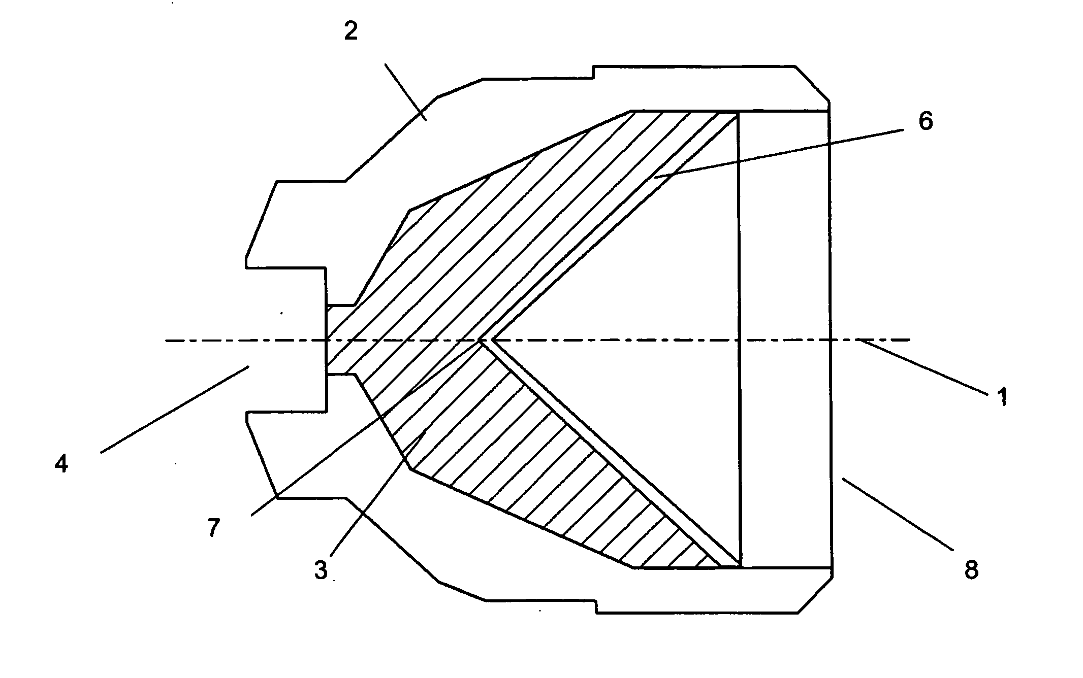
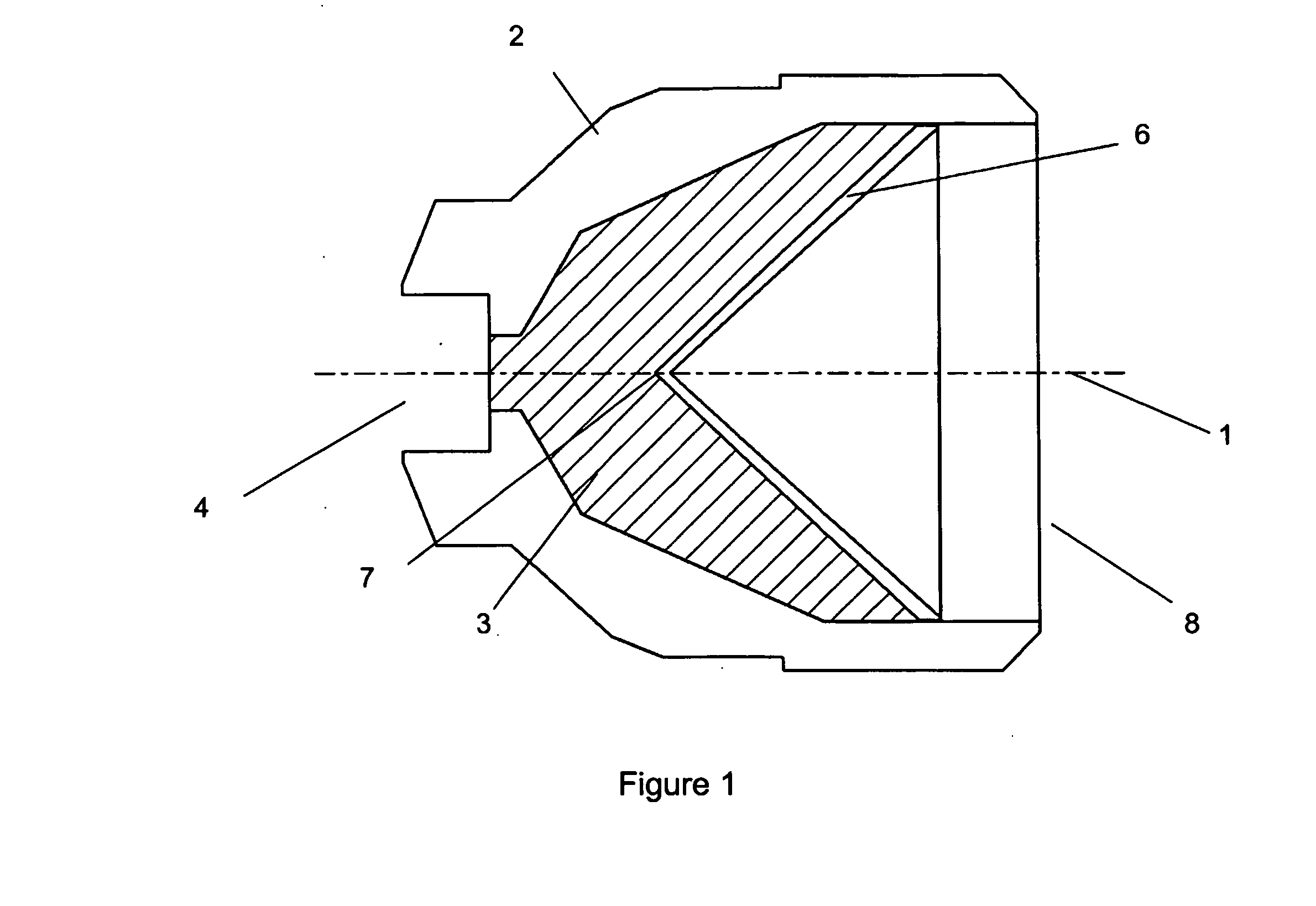
[0052] As shown in FIG. 1 a cross section view of a shaped charge, typically axi-symmetric about centre line 1, of generally conventional configuration comprises a substantially cylindrical housing 2 produced from a metal, polymeric, GRP or reactive material according to the invention. The liner 6 according to the invention, has a wall thickness of typically say 1 to 5% of the liner diameter but may be as much as 10% in extreme cases. The liner 6 fits closely in the open end 8 of the cylindrical housing 2. High explosive material 3 is located within the volume enclosed between the housing and the liner. The high explosive material 3 is initiated at the closed end of the device, proximate to the apex 7 of the liner, typically by a detonator or detonation transfer cord which is located in recess 4.

[0053] A suitable starting material for the liner comprises a stoichiometric mixture of 1 to 10 micron powdered nickel and aluminium with a 0.75 to 5% by weight of powdered binder material....


PUM


Abstract

An oil and gas well shaped charge perforator capable of providing an exothermic reaction after detonation is provided, comprising a housing, a high explosive, and a reactive liner where the high explosive is positioned between the reactive liner and the housing. The reactive liner is produced from a composition which is capable of sustaining an exothermic reaction during the formation of the cutting jet. The composition may be selected from any known formulation which is suitable for use in an oil and gas well perforator, typically the composition will comprise at least one metal and at least one non-metal, wherein the non-metal is selected from a metal oxide, or any non-metal from Group III or Group IV or at least two metals such as to form an intermetallic reaction. Typically at least one of the metals in the invention may be selected from Al, Ce, Li, Mg, Mo, Ni, Nb, Pb, Pd, Ta, Ti, Zn or Zr. The liner composition may preferably be a pressed particulate composition, such that the material is consolidated under pressure to form the desired shape of the liner. To aid consolidation a binder may also be added.

Description

FIELD OF THE INVENTION [0001] The present invention relates to a reactive shaped charge liner for a perforator for use in perforating and fracturing well completions. BACKGROUND TO THE INVENTION [0002] By far the most significant process in carrying out a completion in a cased well is that of providing a flow path between the production zone, also known as a formation, and the well bore. Typically, the provision of such a flow path is carried out by using a perforator, initially creating an aperture in the casing and then penetrating into the formation via a cementing layer, this process is commonly referred to as a perforation. Although mechanical perforating devices are known, almost overwhelmingly such perforations are formed using energetic materials, due to their ease and speed of use. Energetic materials can also confer additional benefits in that they may provide stimulation to the well in the sense that the shockwave passing into the formation can enhance the effectiveness o...

Claims


Application Information

Patent Timeline
IPC IPC(8): F42B12/00E21B43/117F42B1/032
CPCF42B1/032
Inventor BATES, LESLIE RAYMONDBOURNE, BRIAN
Owner WELLS FARGO BANK NAT ASSOC
Why Eureka
Try Eureka