Dripping nozzle device, device for recovering feedstock liquid, device for supplying a feedstock liquid, device for solidifying the surfaces of drops, device for circulation aqueous ammonia solution, and apparatus for droducing ammonium diuranate particles

a technology of dripping nozzles and nozzles, which is applied in the direction of special dispensing means, shaking/oscillating/vibrating mixers, chemical/physical/physico-chemical processes, etc., can solve the problems of not having developed dripping nozzle devices with several dripping nozzles, and not having such nozzle devices comprising nozzles, etc., to achieve uniform particle size and good sphericity

Inactive Publication Date: 2007-03-15
NUCLEAR FUEL INDS
View PDF14 Cites 13 Cited by
  • Summary
  • Abstract
  • Description
  • Claims
  • Application Information

AI Technical Summary

Benefits of technology

[0047] The dripping nozzle device recited in paragraph (1) employs a single vibrator to vibrate the dripping nozzles, and therefore resonance between the dripping nozzles is eliminated, which means that a dripping nozzle is not affected by the other dripping nozzles. Thus the particle diameters of the drops can be controlled easily. Since the dripping nozzle device recited in paragraph (2) has the dripping nozzles, each of which is provided with a flow regulator, the difference in the pressure losses caused by the flow of the feedstock liquid in the nozzles can be reduced, which produces ADU particles of uniform particle size.
[0069] The apparatus for producing ADU particles recited in paragraph (25) is provided with any one of the dripping nozzle device, the device for recovering a feedstock liquid, the device for supplying a feedstock liquid, the device for solidifying the surfaces of liquid drops, and the device for circulating an aqueous ammonia solution. Therefore the apparatus is capable of producing ADU particles of uniform particle size and with good sphericity.

Problems solved by technology

However, technology has not seen such nozzles that are capable of dripping the feedstock liquid in drops with the same volume.
Dripping nozzle devices with several dripping nozzles have not been developed.
However, technology has not seen such nozzle devices comprising nozzles that are capable of dripping the feedstock liquid in the same volume and allowing drops with the same volume to fall.
This difference often causes deformation in ADU particles formed in the aqueous ammonia solution by the dripping, which leads to uranium dioxide particles, produced through the steps of aging the ADU particles, washing the aged, drying the washed, calcining the dried, reducing the calcined, and sintering the reduced, that do not satisfy a required sphericity, a required outer diameter of each particle, a required flawlessness of the inside structure, etc.
This difference also results in a reduction in the yield of the produced uranium dioxide.
We suppose that the afore-mentioned problem is caused by the state where the temperature of the remaining feedstock liquid is raised to room temperature and the viscosity thereof is decreased.
However, only with the flow regulators, it is difficult to make the flow rates of the feedstock liquid to be dripped from the nozzles identical, which results in ADU particles that do not have a uniform diameter.
The film is not strong enough to prevent the drop from deformed by the impact given to the drop when it splashes down.
Also, when an apparatus for producing ADU particles with several dripping nozzles is employed and ammonia gas is sprayed over the drops dripped from the several nozzles and falling toward the solution, it is difficult to uniformly spray each drop with the gas and the drops often had wave-like patterns caused by the sprayed gas on the surfaces thereof.
Therefore, it takes a long time to change uranyl nitrate in the center of the drop to ammonium diuranate, which is one problem.
Another problem is that the reaction between uranyl nitrate and ammonium ions is often insufficient under the conditions where the drops stay still in the aqueous ammonium solution for a predetermined period of time.
Due to these problems, with the conventional apparatus for producing ADU particles, it is difficult to produce ADU particles with a large diameter, which sometimes results in inferior fuel kernels with pores inside, obtained after the treatments in the subsequent steps.
Still another problem is that ADU particles with their central parts remaining unreacted have jelly-like central parts and that the ADU particles are very soft.
Therefore when these ADU particles, the specific gravity of which is large because they include uranium, are piled up and accumulated, ADU particles located near and at the bottom of the aqueous ammonia solution reservoir become deformed, which results in the production of a large quantity of inferior particles with bad sphericity.

Method used


Image

  • Dripping nozzle device, device for recovering feedstock liquid, device for supplying a feedstock liquid, device for solidifying the surfaces of drops, device for circulation aqueous ammonia solution, and apparatus for droducing ammonium diuranate particles
  • Dripping nozzle device, device for recovering feedstock liquid, device for supplying a feedstock liquid, device for solidifying the surfaces of drops, device for circulation aqueous ammonia solution, and apparatus for droducing ammonium diuranate particles
  • Dripping nozzle device, device for recovering feedstock liquid, device for supplying a feedstock liquid, device for solidifying the surfaces of drops, device for circulation aqueous ammonia solution, and apparatus for droducing ammonium diuranate particles

Examples


first embodiment

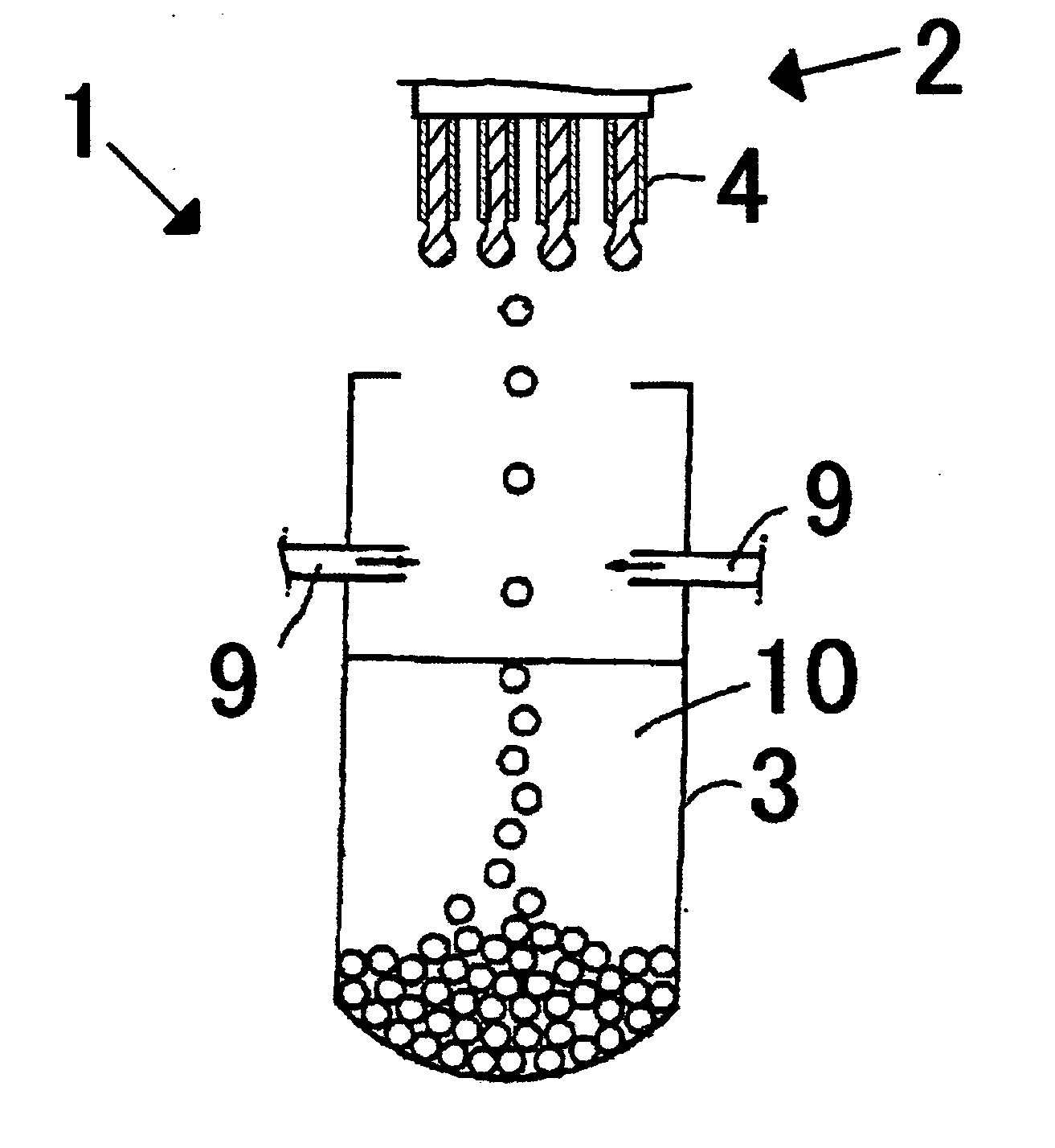
[0093]FIG. 1 shows a first embodiment of the apparatus for producing ADU particles equipped with the dripping nozzle device according to the present invention.

[0094] As shown in FIG. 1, the apparatus for producing ADU particles 1 includes a dripping nozzle device 2, and an aqueous ammonia solution reservoir 3.

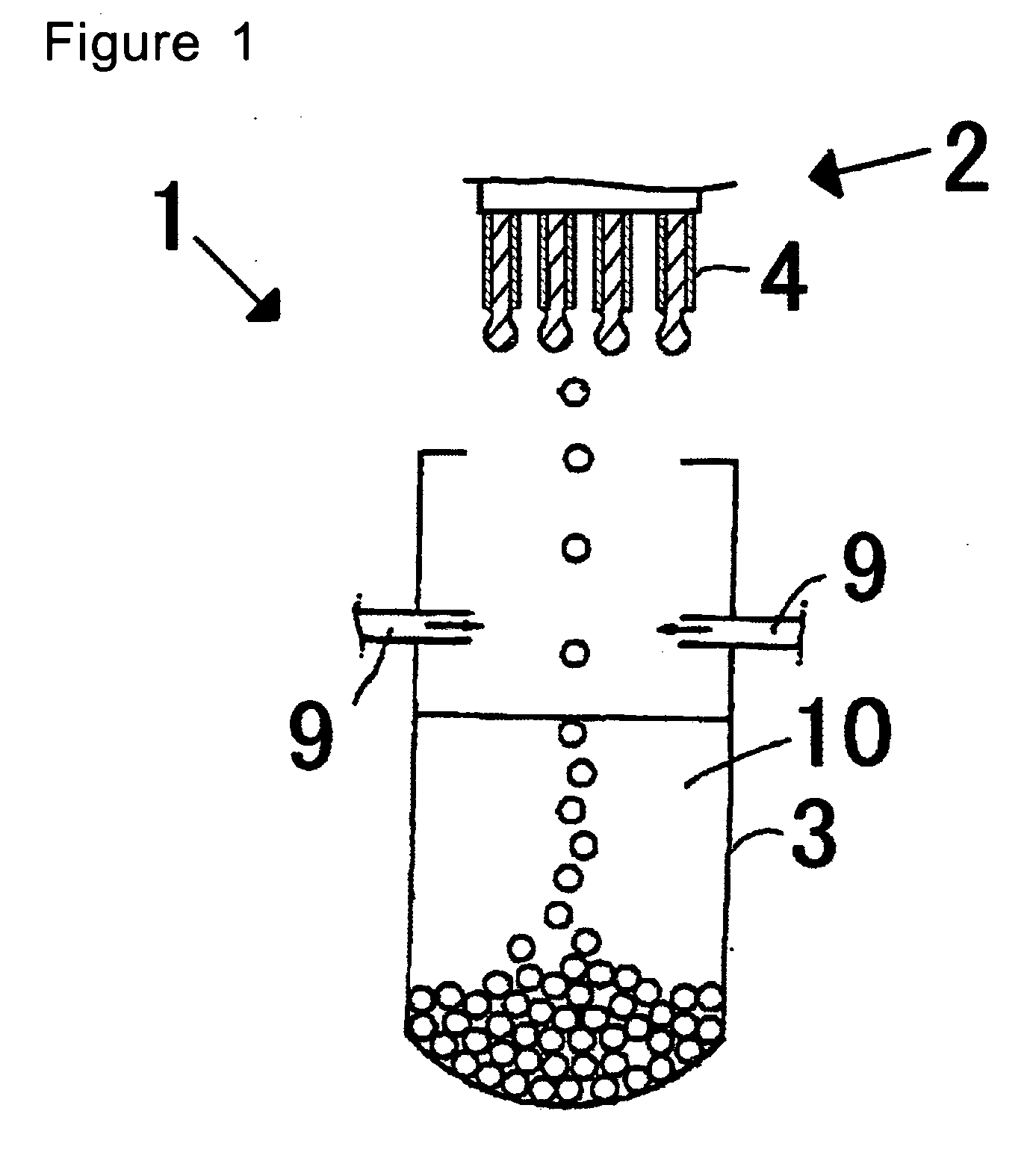
[0095] The dripping nozzle device 4 has several nozzles, for example four nozzles as shown in FIG. 1, and a single vibrator 5 as shown in FIG. 2. In more detail, as shown in FIG. 2, the dripping nozzle device 2 has four nozzles 4, all of which has the same shape of a cylindrical tube, and which four nozzles are vertically arranged at equal spaces with being parallel to each other; a holder 6 for holding the nozzles 4; a holding rod 7 that holds the upper ends of the respective nozzles 4 at the lower end thereof; a vibrator 5 for giving vertical vibration to the nozzles 4 through the holding rod 7; and feedstock liquid supplying pipes 8, an example of the feedstock liquid tran...

second embodiment

[0134] Another embodiment of the apparatus for producing ADU particles according to the invention, which embodiment includes another example of the dripping nozzle according to the present invention is shown in FIG. 5. The apparatus for producing ADU particles of the present invention is not limited to the one shown in FIG. 5.

[0135] The apparatus for producing ADU particles 1 shown in FIG. 5 is capable of producing ADU particles from the feedstock liquid including uranyl nitrate. As shown in FIG. 5, the apparatus 1 has a dripping nozzle device 2 and an aqueous ammonia solution reservoir 3.

[0136] The dripping nozzle device 2, an example according to the present invention, is structured so that it drips the feedstock liquid in the form of a drop. As shown in FIG. 5, the device includes a nozzle or nozzles 4 from which the feedstock liquid fall in drops, and a feedstock liquid receptacle 26, which is an example of the feedstock liquid container that contains a predetermined volume of...

working example 1

[0161] The dripping nozzle device 2 shown in FIGS. 5 and 6 was employed. The nozzle 4 was in the shape of a cylinder with an inner diameter of 0.5 mm and a length of 15 mm. The feedstock liquid receptacle 26 was also in the shape of a cylinder with an inner diameter of 6 mm and a length of 12 mm. A feedstock liquid was prepared by dissolving uranium oxide in nitric acid to produce a uranyl nitrate solution, and mixing the uranyl nitrate solution with polyvinyl alcohol resin and other chemicals. The viscosity of the feedstock liquid was about 60 cP. The uranium content of the liquid including uranyl nitrate was 0.7 mol-U / L.

[0162] The feedstock liquid contained in the feedstock liquid receptacle 26 was dripped from the opening end of the nozzle 4 into an aqueous ammonia solution in the aqueous ammonia solution reservoir 3. The ammonia content of the aqueous ammonia solution was 25% by volume.

[0163] After the reaction between uranyl nitrate included in the feedstock liquid and ammoni...


PUM

PropertyMeasurementUnit
flow rateaaaaaaaaaa
temperatureaaaaaaaaaa
diameteraaaaaaaaaa

Abstract

This invention provides a dripping nozzle device to produce ADU particles with good sphericity, a device for recovering a feedstock liquid to prepare a uniform feedstock liquid, a device for supplying a feedstock liquid to form drops with a uniform volume, a device for solidifying the surfaces of drops so that the drops will not deform easily when they fall onto and hit the surface of an aqueous ammonia solution, a device for circulating an aqueous ammonia solution so that the uranyl nitrate in the drops can be changed to ammonium diuranate completely, to such an extent that uranyl nitrate in the center of each drop is changed to ammonium diuranate, and an apparatus for producing ammonium diuranate particles with good sphericity. The dripping nozzle device is provided with a single vibrator to vibrate nozzles simultaneously. The device for recovering a feedstock liquid recovers the feedstock liquid remaining in the nozzles and mixes it with a fresh feedstock liquid. The device for supplying a feedstock liquid is provided with a light irradiator for irradiating falling drops with light. The device for solidifying the surfaces of drops sprays ammonia gas over each of the paths along which the drops dripping from the nozzles fall. The device for circulating an aqueous ammonia solution enables drops to flow upward in the aqueous ammonia solution in the aqueous ammonia solution reservoir. The apparatus for producing ammonium diuranate utilizes these devices.

Description

TECHNICAL FIELD [0001] The present invention relates to a dripping nozzle device, a device for recovering a feedstock liquid, a device for supplying a feedstock liquid, a device for solidifying the surfaces of drops, a device for circulating an aqueous ammonia solution, and an apparatus for producing ammonium diuranate particles. More particularly, the present invention relates to a dripping nozzle device capable of dripping a feedstock liquid in drops that are suitable for forming ammonium diuranate particles with good sphericity. The present invention also provides a device for recovering a feedstock liquid, capable of recovering a feedstock liquid to be dripped so that uniform deformation-free ammonium diuranate particles can be produced at a high yield. The present invention further relates to a device capable of supplying a feedstock liquid to the nozzle so that the feedstock liquid including uranyl nitrate is allowed to fall in drops, each of which has a same volume. The prese...

Claims


Application Information

Patent Timeline
Patent Type & Authority Applications(United States)
IPC IPC(8): B05B1/00B01J19/00B01J2/06G21C21/02B05B1/14B05B17/06C01G43/00C01G43/01G21C3/62
CPCB01J2/06B05B1/14B05B17/0607C01G43/00C01G43/01Y02E30/38G21C3/64G21C21/02G21Y2002/302G21Y2004/30G21Y2004/40C01P2004/32Y10T137/8158Y02E30/30
Inventor OKUBO, KAZUTOSHITAKAHASHI, MASASHITAKAYAMA, TOMOONISHIMURA, KAZUHISAHONDA, MASAKI
Owner NUCLEAR FUEL INDS
Why Eureka
Try Eureka