RFID transponder and RFID transponder chip

a technology of rfid transponder and rfid transponder, which is applied in the direction of instruments, heat measurement, electric signalling details, etc., can solve problems such as inoperableness, and achieve the effect of accurate measuremen

Inactive Publication Date: 2007-03-15
FUJITSU SEMICON LTD
View PDF5 Cites 44 Cited by
  • Summary
  • Abstract
  • Description
  • Claims
  • Application Information

AI Technical Summary

Benefits of technology

[0013] In a preferable example of the embodiment of the present invention, a distance between the temperature sensor and the data control circuit is longer than a distance between the temperature sensor and at least one of the memory control circuit and the nonvolatile memory. For example, at least one of the memory control circuit and the nonvolatile memory is disposed between the temperature sensor and the data control circuit. Alternatively, a distance between the temperature sensor and the power supply control circuit is longer than a distance between the temperature sensor and at least one of the memory control circuit and the nonvolatile memory. For example, at least one of the memory control circuit and the nonvolatile memory is disposed between the temperature sensor and the power supply control circuit. This can prevent the temperature sensor from being influenced by heat generated from the data control circuit and the power supply control circuit. As a result, the temperature of the RFID transponder and its ambient temperature can be accurately measured.

Problems solved by technology

That is, during a period in which the temperature sensor is measuring the temperature, the nonvolatile memory and the memory control circuit are not supplied with the second power supply voltage and thus do not operate.

Method used


Image

  • RFID transponder and RFID transponder chip
  • RFID transponder and RFID transponder chip
  • RFID transponder and RFID transponder chip

Examples


first embodiment

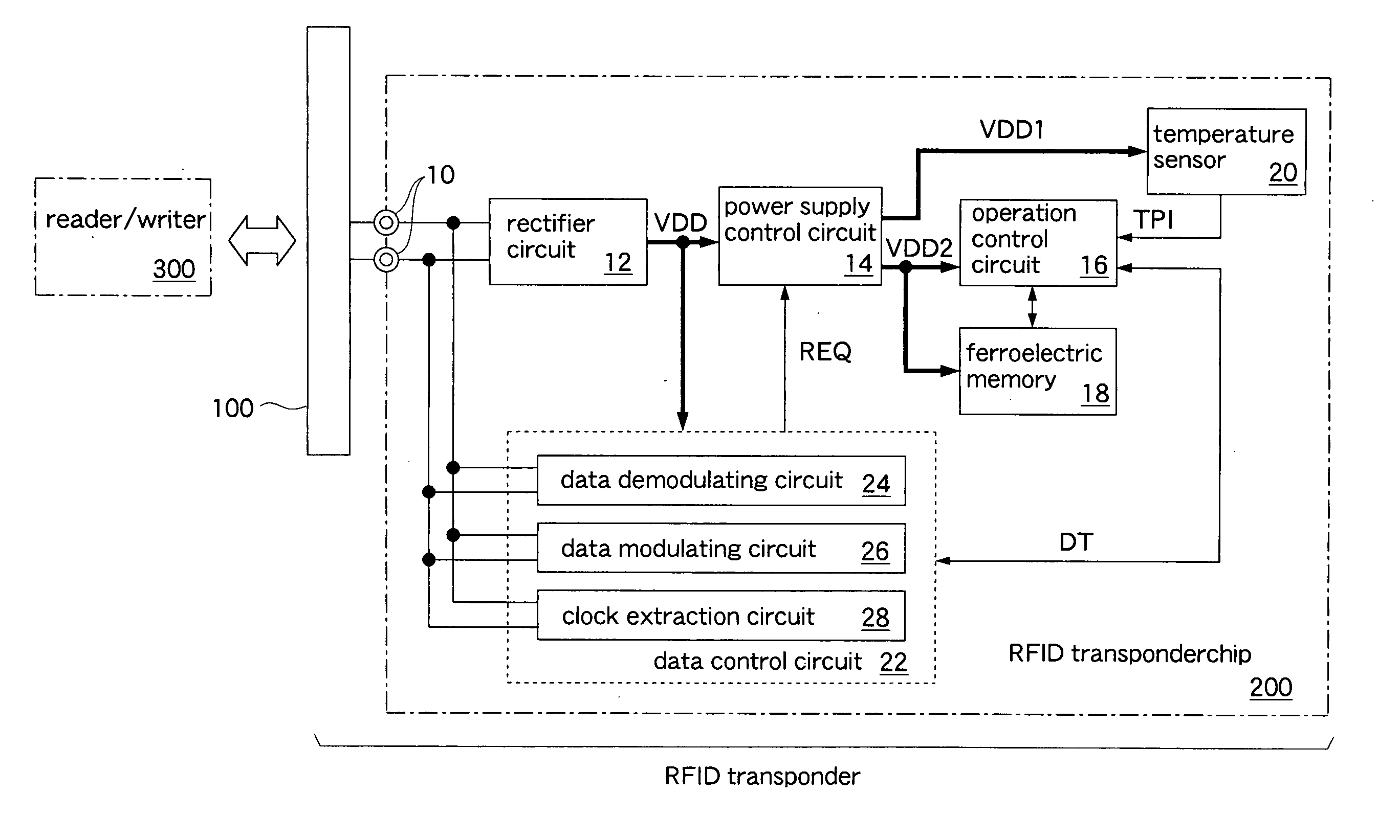
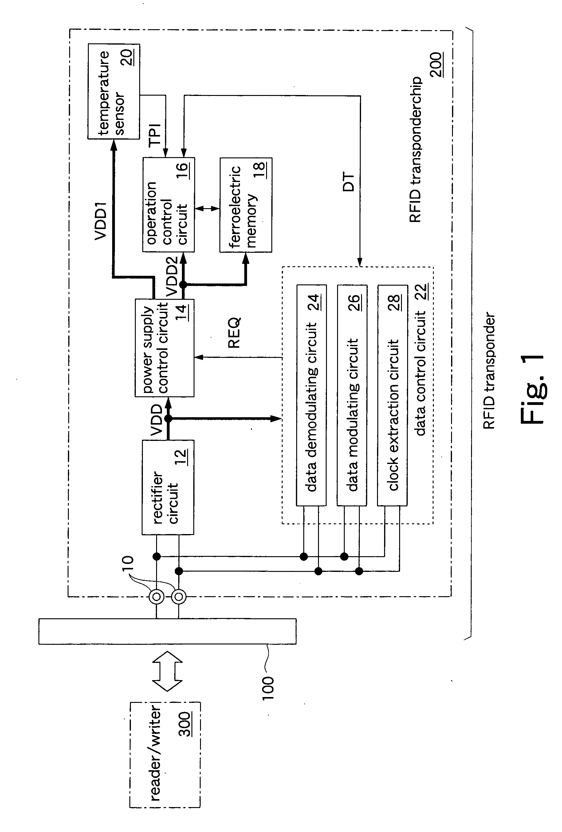
[0023]FIG. 1 shows an RFID transponder and an RFID transponder chip of the present invention. The RFID transponder includes a dipole antenna 100, an RFID transponder chip 200, and a resin board (not shown) on which the RFID transponder chip 200 is mounted. The dipole antenna 100 is formed of a metal leaf printed on the resin board. The RFID transponder chip 200 is formed on a silicon substrate by using a CMOS process. A thickness of the RFID transponder chip 200 is set to 100 μm by polishing a rear surface of a silicon wafer. In this embodiment, the thickness of the chip is set to 100 μm, but further reducing the thickness of the chip results in a larger heat-resistance in a direction along a front surface of the silicon substrate. Consequently, the transmission of heat, which is generated by the operation of a circuit, to another circuit via the silicon substrate can be reduced to a minimum.

[0024] The RFID transponder is attached to, for example, a perishable food (vegetable, meat,...

third embodiment

[0060]FIG. 7 shows the operations of the RFID transponder of the Detailed description of the same operations as the above-described operations in FIG. 4 will be omitted. The operations shown in FIG. 7 are executed when, for example, the reader / writer 300 installed in a bed of a truck transmits power and a temperature measuring request to each of the RFID transponders every 10 minutes. The readers / writers 300 in a warehouse and a showcase also transmit power and the temperature measuring requests to the RFID transponder at the same intervals.

[0061] In this embodiment, the main power supply voltage VDD is constantly supplied to the RFID transponder chip 200B. Therefore, the data control circuit 22 is capable of constantly operating, and in response to the temperature measuring request from the reader / writer 300, it outputs a request signal REQ to the power supply control circuit 14. In response to the request signal REQ, the power supply control circuit 14 starts outputting a first p...

second embodiment

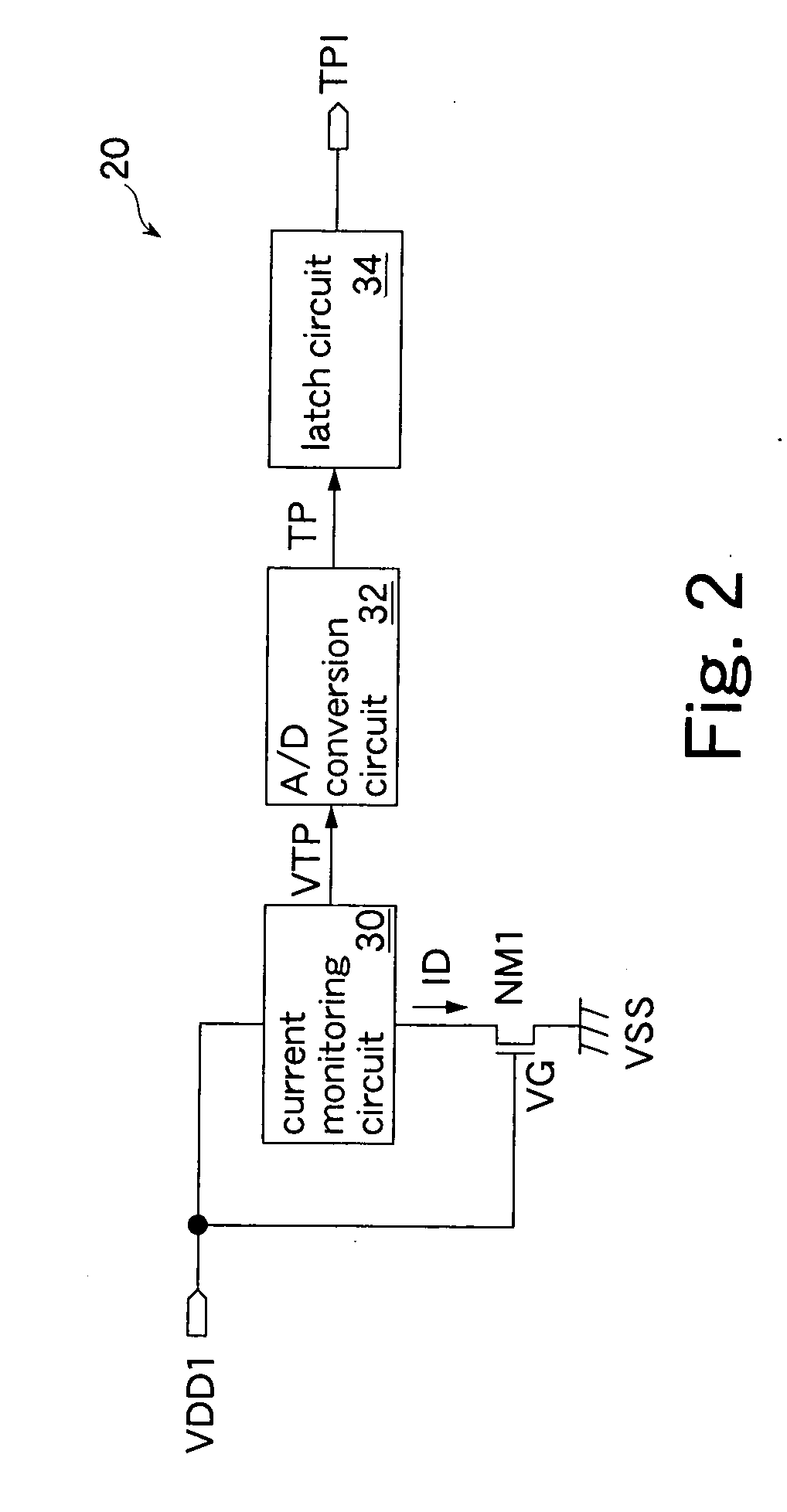
[0065] The above second embodiment has described the example where the constant current IC is supplied to the drain of the nMOS transistor NM1 and the temperature is measured based on the drain voltage VD that varies depending on temperature. The present invention is not limited to such an embodiment. Another possible example is to supply a constant voltage to the drain-source of the nMOS transistor NM1 and measure the temperature based on a drain current that varies depending on temperature.

[0066] The above embodiments have described the examples where the carrier frequency of 950-956 MHz is used for communication with the readers / writers 300 and the RFID transponder. The present invention is not limited to such embodiments. For example, a carrier frequency of 13.56 MHz (electromagnetic field) may be used for communication between the readers / writers 300 and the RFID transponder. In this case, instead of the dipole antenna 100, a coil antenna is mounted on the RFID transponder.

[00...


PUM


Abstract

A nonvolatile memory is accessed by a memory control circuit and stores temperature information indicating a temperature measured by a temperature sensor. A power supply control circuit supplies a first power supply voltage to the temperature sensor in response to a request for temperature measurement received via an antenna, and supplies a second power supply voltage to the nonvolatile memory and the memory control circuit after the temperature sensor measures the temperature. While the temperature sensor is measuring the temperature, the nonvolatile memory and the memory control circuit do not operate and thus do not generate heat. Therefore, the temperature sensor can accurately measure the temperature without being influenced from the heat generation caused by the operation of circuits in an RFID transponder.

Description

CROSS REFERENCE TO RELATED APPLICATION [0001] This application is a continuation application of International Application PCT / JP2004 / 009646, filed Jul. 7, 2004, and designating the U.S. BACKGROUND OF THE INVENTION [0002] 1. Field of the Invention [0003] The present invention relates to an RFID transponder transmitting / receiving data by radio and an RFID transponder chip included in the RFID transponder. [0004] 2. Description of the Related Art [0005] In recent years, an RFID transponder has been drawing attention as a key device for realizing a ubiquitous network. The use of RFID transponders in place of barcodes and the like for product identification eliminates the need to manually read barcodes and the like. The use of RFID transponders remarkably improves product management efficiency. RFID transponders are applicable not only to product identification but also to tracking of the history of products in manufacturing processes (production processes), the history of product manage...

Claims


Application Information

Patent Timeline
Patent Type & Authority Applications(United States)
IPC IPC(8): H04Q5/22
CPCG01K1/022G06K19/0723G06K19/0717G01K1/14
Inventor TOMIOKA, TAKESHI
Owner FUJITSU SEMICON LTD
Why Eureka
Try Eureka