
Noise reducing apparatus, method and program and sound pickup apparatus for electronic equipment

Inactive Publication Date: 2007-03-15
SONY CORP
View PDF2 Cites 75 Cited by
  • Summary
  • Abstract
  • Description
  • Claims
  • Application Information

AI Technical Summary

Benefits of technology

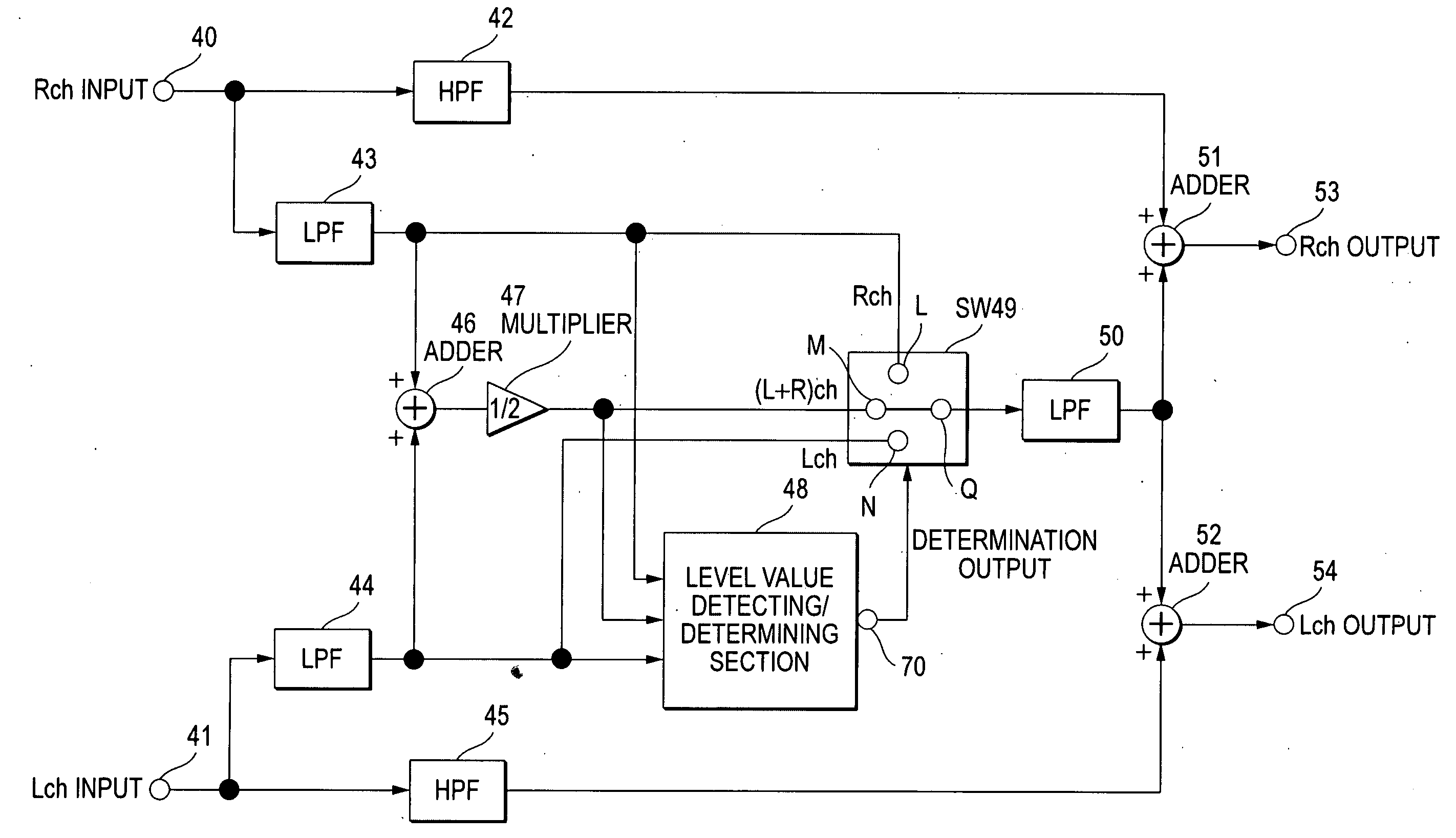
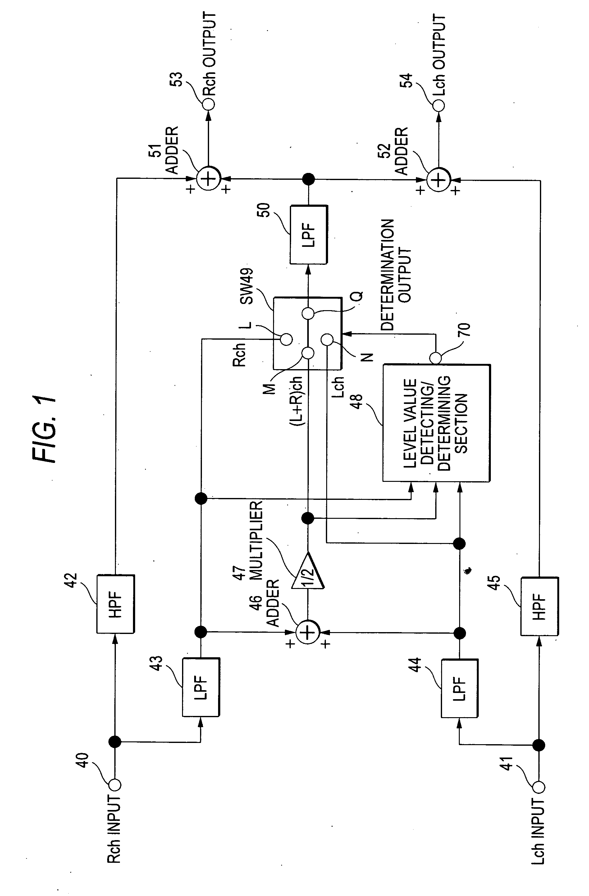
[0042] According to the embodiments of the invention, since minimum (or minimum value) selecting processing is performed in wind noise reduction processing that performs monaural conversion (averaging) in the past, the only in-phase component included in multiple signals can be strongly extracted. The strongly related signals such as imageable sound signals from contained microphones of a video camera, for example, may be extracted as an in-phase component while unrelated signals such as wind noise signals are largely removed. Thus, a noise reducing apparatus, method and program and sound pickup apparatus for electronic equipment can be obtained which can increase the effect of reducing the wind noise component.
[0050] Furthermore, a noise reducing apparatus, method and program and sound pickup apparatus for electronic equipment thereof can be obtained which can have a higher wind noise reduction effect than prior arts even when the combination of the wind noise reducing processing of the invention and the conventional wind noise reducing processing is implemented.

Problems solved by technology

Furthermore, due to the swirling airflow (which may be called Kalman swirl) occurring in the vicinity of a microphone, the wind noise signals from multiple microphones approximate to random signals having less correlation than audio signals.
The unrelated components may result from an imbalance in characteristics of L / Rch circuits in the previous circuit of the wind noise reducing circuit that reduces wind noise included in audio signals of the L / Rch based on multiple audio signals from multiple microphones, forms of microphones used for picking-up, forms and attaching method of surrounding wind preventing devices (such as a sponge and wire netting), differences in spaces between microphones, and conversion of audio signals from multiple microphones used for picking-up to L / Rch audio signals by a stereo conversion processing circuit.
Especially, the use of omni-directional microphones may result in making a slight difference and therefore no sense of stereo.

Method used


Image

  • Noise reducing apparatus, method and program and sound pickup apparatus for electronic equipment
  • Noise reducing apparatus, method and program and sound pickup apparatus for electronic equipment
  • Noise reducing apparatus, method and program and sound pickup apparatus for electronic equipment

Examples


second embodiment

[0075] Next, a two-channel wind noise reducing apparatus according to the invention will be described. In the block diagram shown in FIG. 5, wind noise is reduced without the monaural conversion of a wind noise band unlike the wind noise reducing apparatus in FIG. 1. First of all, Rch and Lch signals input from input terminals 71 and 72 are input to an HPF 75 and an LPF 73 and an HPF 76 and an LPF 74, respectively. The Rch low frequency signal from the LPF 73 is input to an adder 77, a first level value detecting / determining section 79 and a fixed contact R of an SW 81. The Lch low frequency signal from the LPF 74 is input to an adder 77, a second level value detecting / determining section 80 and a fixed contact V of an SW 82.

[0076] The output of the adder 77 is multiplied by ½ by a multiplier 78 and is input, as a (L+R)ch signal, to the first and second level value detecting / determining sections 79 and 80 and fixed contacts S and U of the SWs 81 and 82. Here, the first and second le...

third embodiment

[0080] Next, a noise reducing apparatus according to the invention will be described with reference to the block diagram in FIG. 7. The same reference numerals with letters a and b are given to the corresponding components as those of the noise reducing apparatus in the block diagram shown in FIG. 1 and the detail description will be omitted herein. As indicated by the frequency band characteristic curb shown in FIG. 8, FIG. 7 includes a band 3, which is not a wind noise band, and the case that the wind noise band frequency is divided in bands into bands 1 and 2 will be described.

[0081] The Rch and Lch signals input from input terminals 111 and 112 are first divided in bands by band pass filters (called BPFs 1-115 and 1-116, BPFs 2-117 and 2-118 and BPFs 3-113 and 3-114), and each of the wind noise band frequencies of the band 1 and 2 is processed by the BPFs 1-115 and 1-116 and BPFs 2-117 and 2-118. First of all, the minimum value of the Rch and Lch signals from the BPFs 1-115 and ...

fifth embodiment

[0084] Having described the construction for wind noise reduction in two Lch and Rch channels, the invention is applicable to multi-channels including three or more channels. With reference to FIG. 11, a three-channel noise reducing apparatus according to the invention will be described. First of all, Rch, center channel (called Cch hereinafter) and Lch signals are input from input terminals 180, 181 and 182 and are divided in bands into a wind noise band and a non wind noise band by an HPF 183 and an LPF 186, an HPF 184 and an LPF 187 and an HPF 185 and an LPF 188, respectively. The wind noise band signals Rch, Cch and Lch from the LPFs are input to an SW 192 and a level value detecting / determining section 191.

[0085] The outputs from the LPFs 186, 187 and 188 are also input to an adder 189 and are all added therein. Then, the result undergoes multiplication processing in a ⅓ multiplier 190 and is averaged therein. Then, the result is input as a (L+R+C)ch signal to an SW 192 and a l...


PUM


Abstract

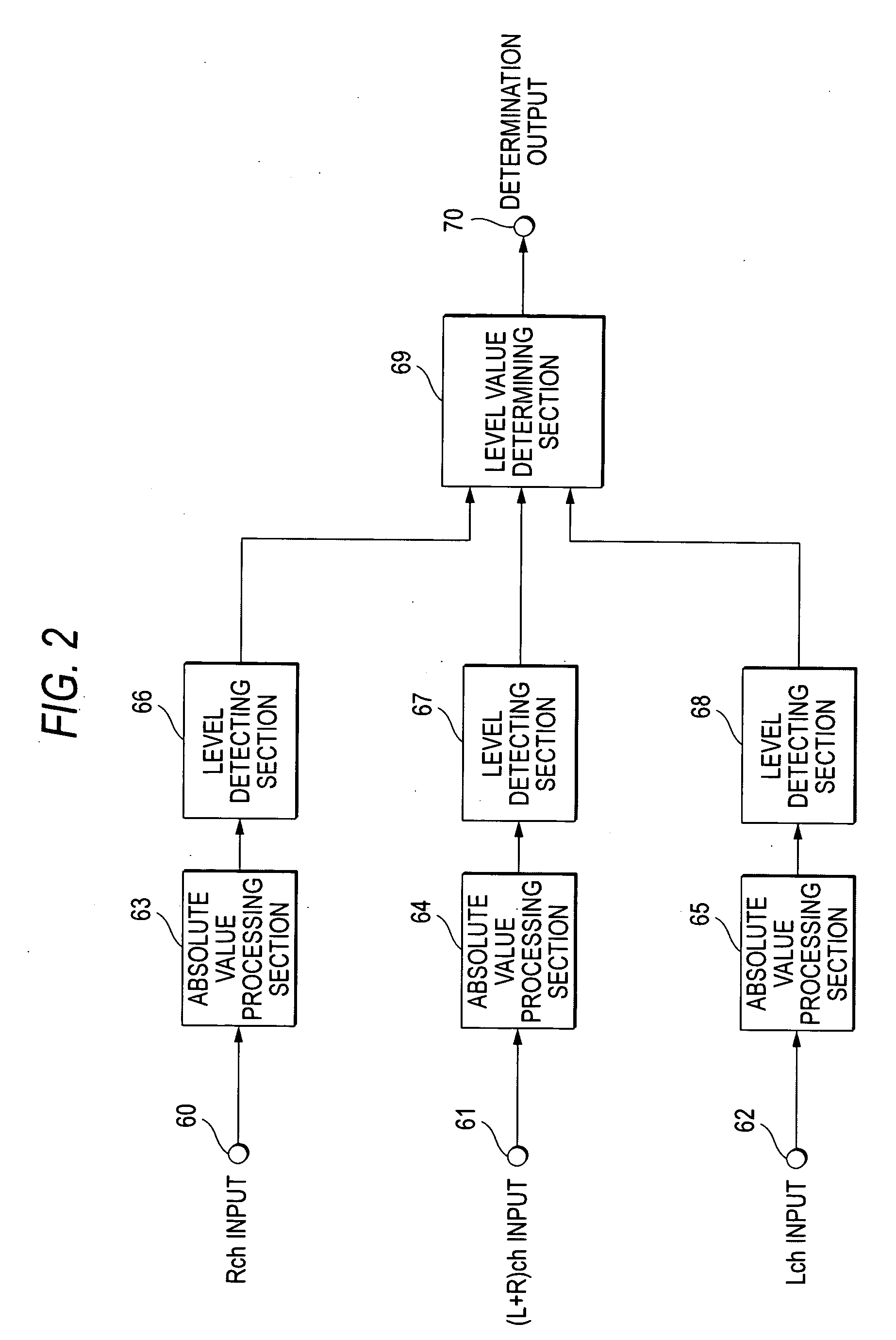
A noise reducing apparatus is disclosed, which includes: input means for inputting multiple audio signals from multiple audio channels; multiple band extracting means for extracting a predetermined band from the multiple audio signals; calculating means for averaging signals from the multiple band extracting means; multiple first level detecting means for detecting the signal levels in a predetermined period of time of the signals from the multiple band extracting means; second level detecting means for detecting the signal level in a predetermined period of time of the signal from the calculating means; selecting means for selecting, for each of the predetermined period of times, the signal having the lowest level value of the level values detected by the multiple first level detecting means and the second level detecting means; band limiting means for limiting the band of the signal from the selecting means; and band synthesizing means for band-synthesizing the signal from the band limiting means and the signal in a band, which is not extracted by the multiple band extracting means, for each audio channel, wherein the output of the band synthesizing means is an audio channel output signal.

Description

CROSS REFERENCES TO RELATED APPLICATIONS [0001] The present invention contains subject matter related to Japanese Patent Application JP2005-264157 filed in the Japanese Patent Office on Sep. 12, 2005 the entire contents of which being incorporated herein by reference. BACKGROUND OF THE INVENTION [0002] 1. Field of the Invention [0003] The present invention relates to a noise reducing apparatus, method and program and sound pickup apparatus for electronic equipment, which allow the reduction of noise in an electric circuit due to the wind through a microphone and, in particular, a noise reducing apparatus, method and program and sound pickup apparatus for electronic equipment, which minimize, select and re-synthesize multiple microphone signals for each predetermined period of time. [0004] 2. Description of the Related Art [0005] In order to prevent wind noise in the outdoor picking-up with a large broadcasting or industrial video camera in the past, a wind preventing device called w...

Claims


Application Information

Patent Timeline
IPC IPC(8): H04B15/00G10L21/0208
CPCG10L19/008G10L21/0208H04S2420/07H04S1/00H04R2410/07H04R3/00H04R5/00
Inventor OZAWA, KAZUHIKO
Owner SONY CORP
Learn More