Method of alignment of an optical module and an optical module using thereof
a technology of optical modules and alignment methods, applied in the direction of optical elements, instruments, semiconductor lasers, etc., can solve the problems of inapplicability, method defects, manufacturing methods as described above are not adapted,
- Summary
- Abstract
- Description
- Claims
- Application Information
AI Technical Summary
Benefits of technology
Problems solved by technology
Method used
Image
Examples
first embodiment
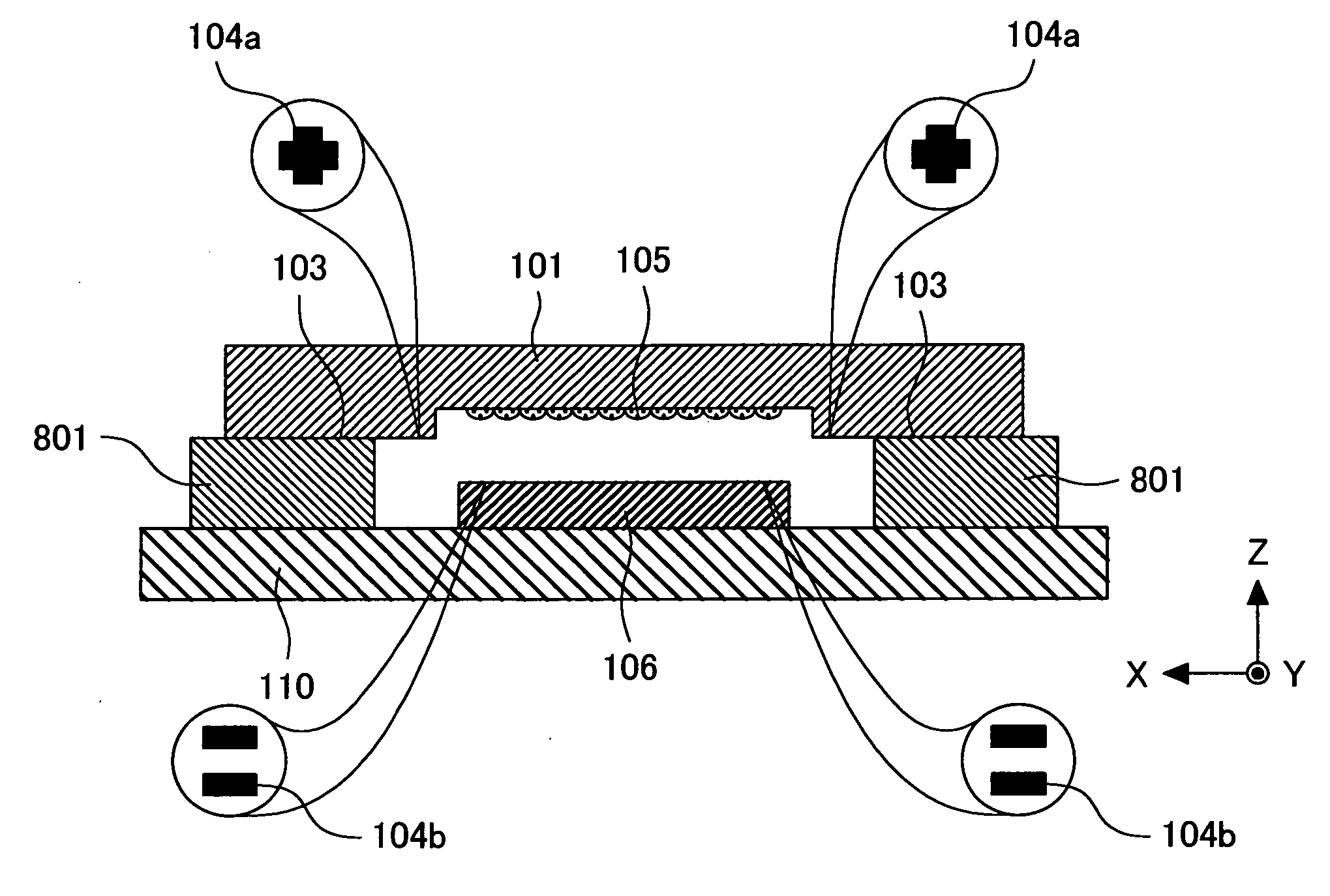
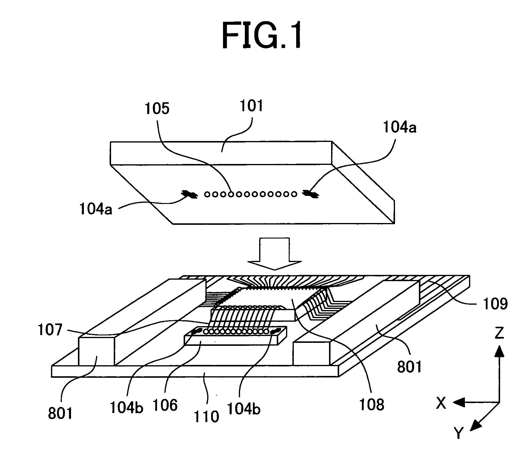
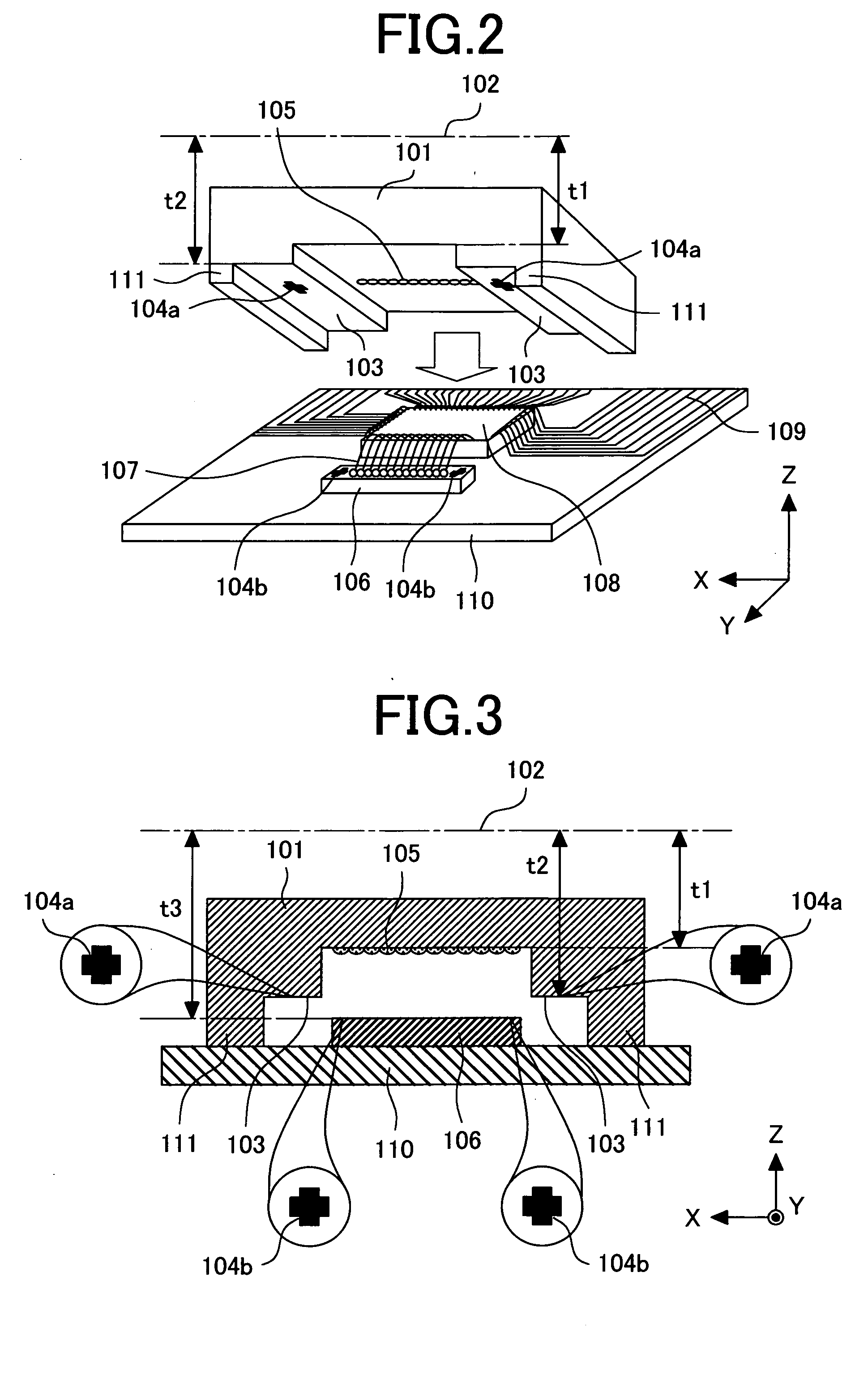
[0036]FIG. 2 is a view illustrating a case where position adjustment with alignment marks according to a first embodiment of the present invention is applied to an optical module. FIG. 3 is a cross-sectional view illustrating an optical module in which position adjustment with the alignment marks according to the first embodiment is applied, and the cross-section is taken at a position of a lens array 105. An IC 108 and a surface emitting laser 106 are mounted on a board 110 for a photonic device. An alignment mark 104b is provided on a top surface of the surface emitting laser 106. Wiring 107 is provided between the IC 108 and the surface emitting laser 106, and electric wiring 109 for connection to an external circuit is provided on the IC 108. A lens member 101 with the lens array 105 formed thereon is arranged at a position opposite to the surface emitting laser 106. In the first embodiment, a supporting member 111 is formed as a spacer at each of the two end portions in place o...
second embodiment
[0044] In the first embodiment, the alignment mark 104a is provided on the end face 103 of the protruding portion of the lens member 101 and also the alignment mark 104b is provided on the surface emitting laser 106. A second embodiment of the present invention does not use the alignment mark 104b for the surface emitting laser 106.
[0045]FIG. 10A to FIG. 10C are plan views each illustrating a top surface of the surface emitting laser 106. FIG. 10A is a view corresponding to FIG. 5, and in FIG. 10A, light-emitting devices or light-receiving devices 1101 are shown in place of the lens array 105. FIG. 10A illustrates an example of the surface emitting laser 106 according to the first embodiment, and the alignment mark 104b is provided thereon.
[0046]FIG. 10B illustrates a case different from that shown in FIG. 10A, in which a line surrounding the light-receiving devices 1101 and electrodes 401 is used in place of the alignment mark 104b described above. FIG. 10C illustrates an example...
third embodiment
[0048]FIG. 11 is a cross-sectional view illustrating the configuration similar to that shown in FIG. 3, in which alignment marks 104b and 104a are provided on a surface of the board 110 for a photonic device and at an end of the end face 103 of a protruding portion of the lens member respectively. The alignment mark 104b is used to precisely mount the surface emitting laser 106 on the board 110 for a photonic device, and also functions as a reference for positioning the lens member 101. As a result, relative positions of the surface emitting laser 106 and the lens member 101 can be decided correctly.
PUM
 Abstract
Description
Claims
Application Information
 - R&D
- Intellectual Property
- Life Sciences
- Materials
- Tech Scout
- Unparalleled Data Quality
- Higher Quality Content
- 60% Fewer Hallucinations
Browse by: Latest US Patents, China's latest patents, Technical Efficacy Thesaurus, Application Domain, Technology Topic, Popular Technical Reports.
© 2025 PatSnap. All rights reserved.Legal|Privacy policy|Modern Slavery Act Transparency Statement|Sitemap|About US| Contact US: help@patsnap.com


