Fuel cell

US20070059575A1Inactive Publication Date: 2007-03-15KK TOSHIBA

Image

  • Fuel cell
  • Fuel cell
  • Fuel cell

Examples


example 1

[0097]

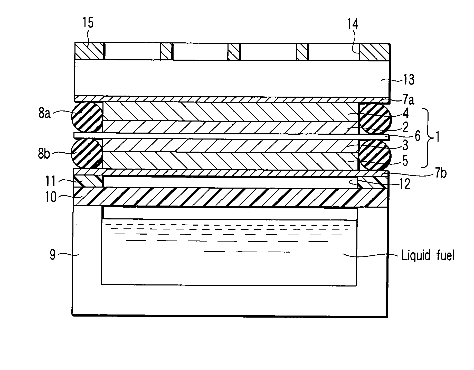
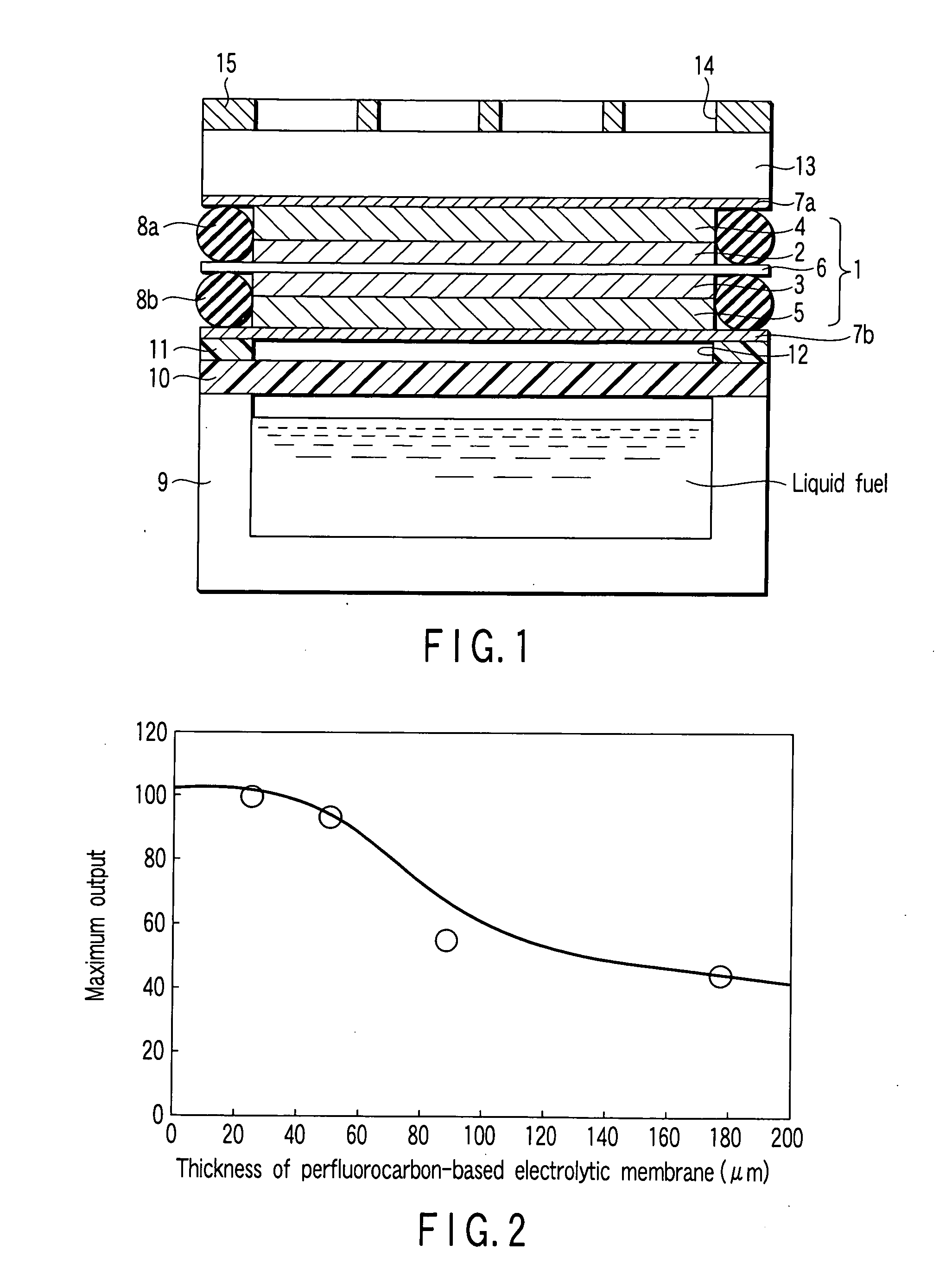
[0098] To catalyst-supported (Pt:Ru=1:1) carbon black for anode, a perfluorocarbon sulfonic acid solution, water and methoxypropanol were added, and the catalyst-supported carbon black was dispersed, thus preparing a paste. The obtained paste was applied onto porous carbon paper, which would serve as an anode gas diffusion layer, and thus an anode catalyst layer having a thickness of 450 μm was obtained.

[0099]

[0100] To catalyst-supported (Pt) carbon black for cathode, a perfluorocarbon sulfonic acid solution, water and methoxypropanol were added, and the catalyst-supported carbon black was dispersed, thus preparing a paste. The obtained paste was applied onto porous carbon paper, which would serve as a cathode gas diffusion layer, and thus a cathode catalyst layer having a thickness of 400 μm was obtained.

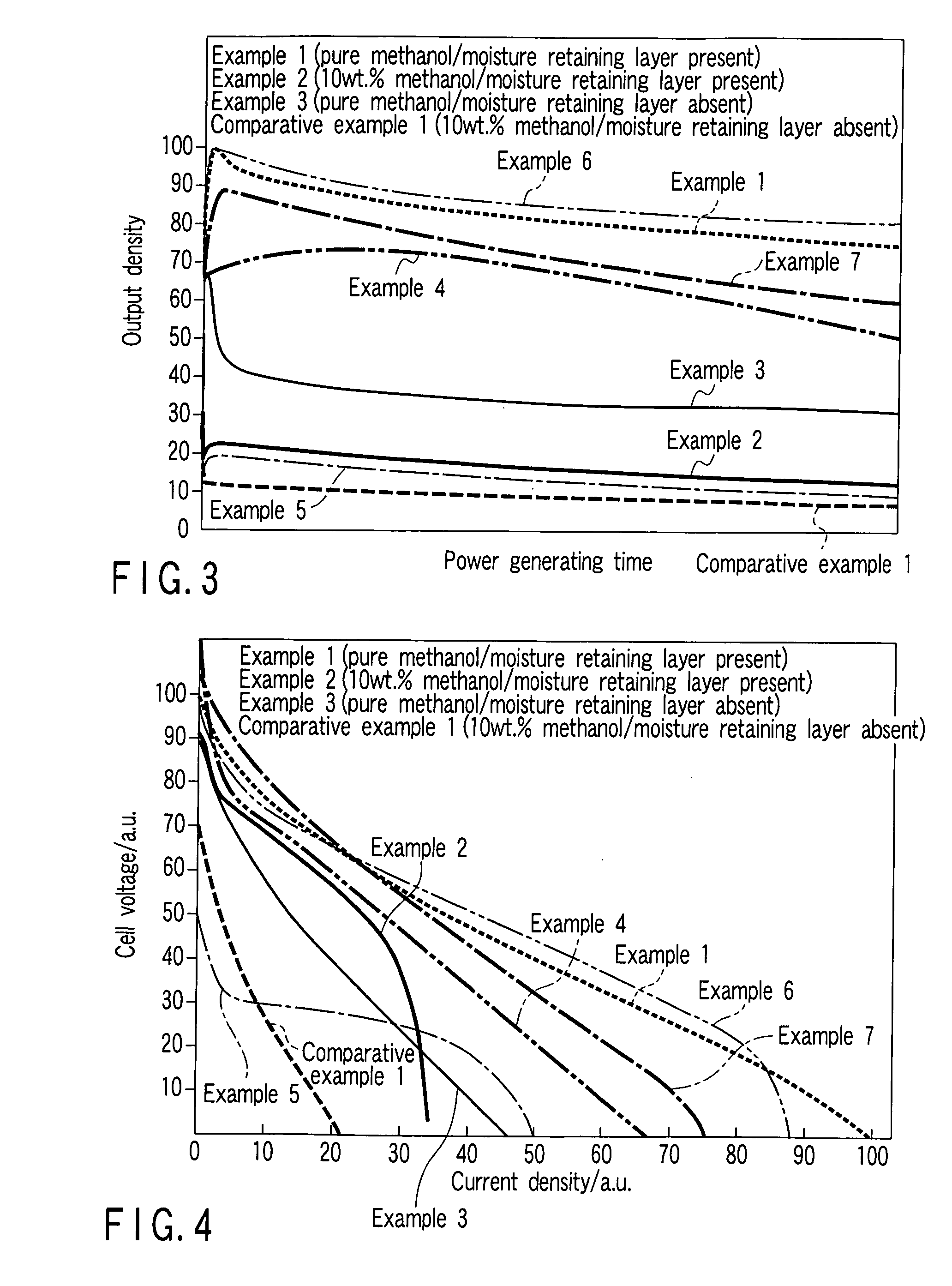
[0101] A perfluorocarbon sulfonic acid film (nafion film of Du Pont) having a thickness of 30 μm and a water content rate of 10 to 20% by weight was sandwiched between the ...

example 2

[0105] An internal evaporation direct methanol fuel cell was assembled in a similar manner to that of Example 1 described above except that a methanol aqueous solution having a concentration of 10% by weight was contained in the fuel tank in place of pure methanol.

example 3

[0106] An internal evaporation direct methanol fuel cell was assembled in a similar manner to that of Example 1 described above except that a surface layer is stacked directly on the cathode diffusion layer, in other words, the moisture retaining plate is not provided between the cathode diffusion layer and the surface layer.


PUM


Abstract

A fuel cell includes a cathode catalyst layer, an anode catalyst layer, a proton-conductive membrane provided between the cathode catalyst layer and the anode catalyst layer, and a fuel transmitting layer that supplies a vaporized component of a liquid fuel to the anode catalyst layer. Water generated in the cathode catalyst layer is supplied to the anode catalyst layer via the proton-conductive membrane. The liquid fuel is one of a methanol aqueous solution having a concentration of over 50% by molar and liquid methanol.

Description

CROSS REFERENCE TO RELATED APPLICATIONS [0001] This is a Continuation Application of PCT Application No. PCT / JP2005 / 008713, filed May 12, 2005, which was published under PCT Article 21(2) in Japanese. [0002] This application is based upon and claims the benefit of priority from prior Japanese Patent Application No. 2004-145187, filed May 14, 2004, the entire contents of which are incorporated herein by reference.BACKGROUND OF THE INVENTION [0003] 1. Field of the Invention [0004] The present invention relates to a fuel cell. [0005] 2. Description of the Related Art [0006] In recent years, various types of electronic devices such as personal computers and mobile telephones have been reduced in size as the semiconductor technology advances, and there have been attempts in which a fuel cell is used as the power source of a small-sized device. A fuel cell has such advantages that it can generate electrical power merely by supplying the fuel and oxidizer thereto, and it can continuously g...

Claims


Application Information

Patent Timeline
15 Mar 2007
Publication
US20070059575A1
IPC
H01M8/10; H01M8/02; H01M8/04
CPC
H01M8/04089; H01M8/04171; H01M8/04194; Y02E60/523; H01M8/1011; H01M2008/1095; H01M8/04291; Y02E60/50
Inventors
KAN, HIROFUMI; NEGISHI, NOBUYASU