
Electrode wire material and solar cell having connection lead wire formed of the wire material

a technology of electrode wire and lead wire, which is applied in the direction of manufacturing tools, welding/cutting media/materials, and manufacturing tools, etc., can solve the problems of connection lead wire, soldering failure, and easy insufficient heat transmission from the semiconductor substrate side to the hot-dip solder plated layer, etc., to improve the bonding durability of the electrode wire material, improve the solderability of the soldered part formed, and facilitate flattening

Inactive Publication Date: 2007-03-22
NEOMAX MATERIALS
View PDF7 Cites 15 Cited by
  • Summary
  • Abstract
  • Description
  • Claims
  • Application Information

AI Technical Summary

Benefits of technology

"The invention relates to an electrode wire material used for connecting solar cells. The material has a hot-dip solder plated layer with a flat surface, which is important for good solderability. The invention provides a solution without the need for complicated flattening equipment and tools. The electrode wire material has a recessed part where molten solder is stored and the solder plated layer fills the recessed part, resulting in a flat surface. This material has excellent solderability and is suitable for use in solar cells."

Problems solved by technology

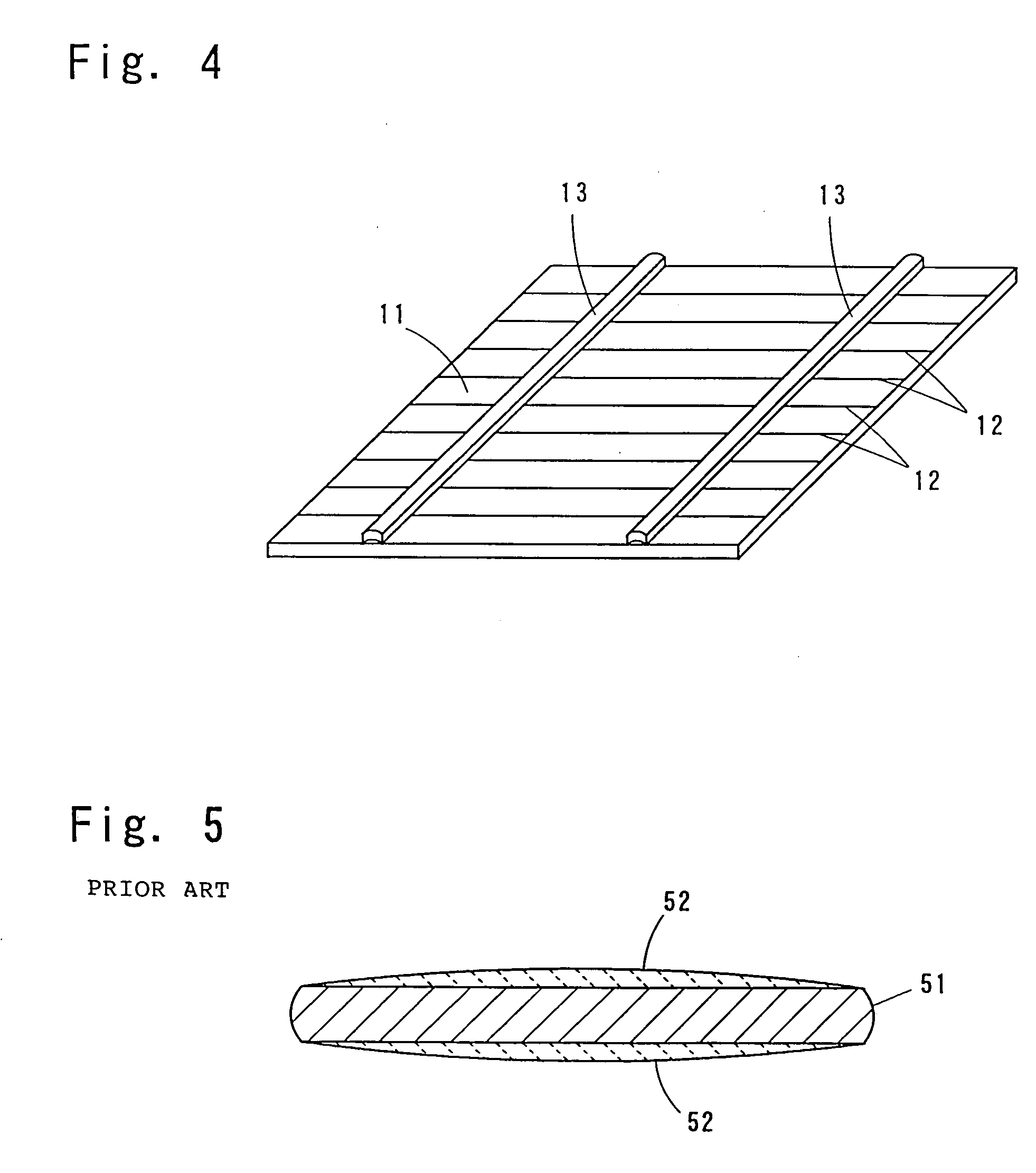
However, as shown in FIG. 5, since the hot-dip solder plated layer of the electrode wire material has the hill-like shape expanded in the center part, at the time of soldering the electrode wire material to the front electrodes of the semiconductor substrate, the contact region of the solder belt formed previously on the surface of the semiconductor substrate for easy electric communication to the front electrodes and the hot-dip solder plated layer becomes narrow and the heat transmission from the semiconductor substrate side to the hot-dip solder plated layer easily tends to be insufficient.
Hence, soldering failure tends to occur.
In an extreme case, there occurs a problem that the connection lead wires come out of the semiconductor substrate during handling the solar cell.

Method used

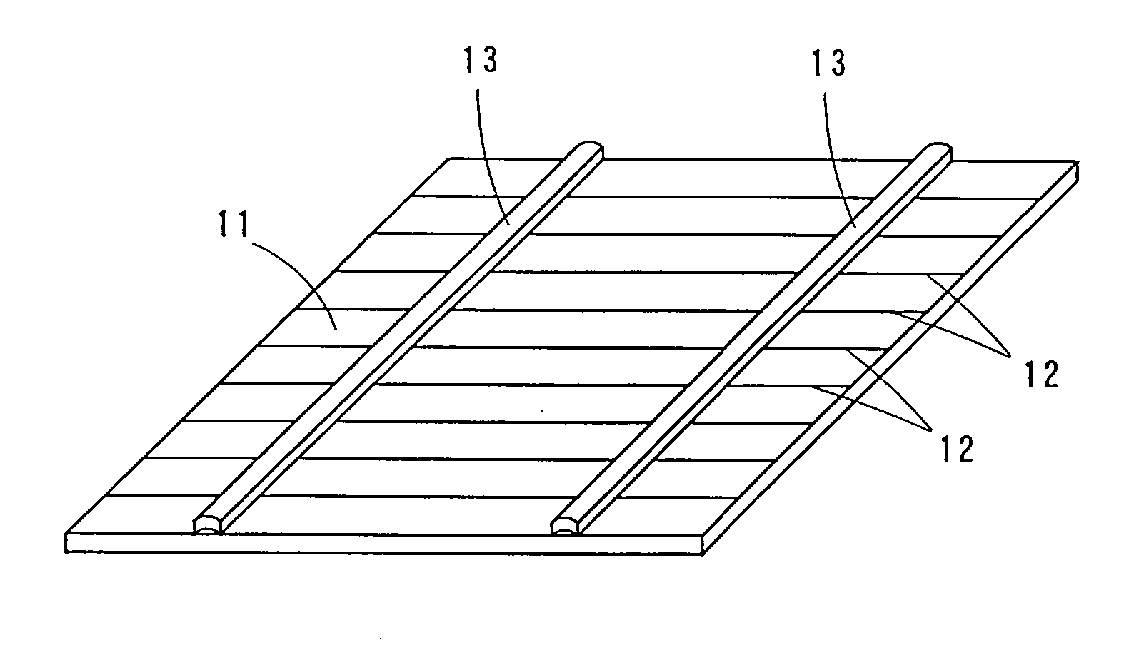
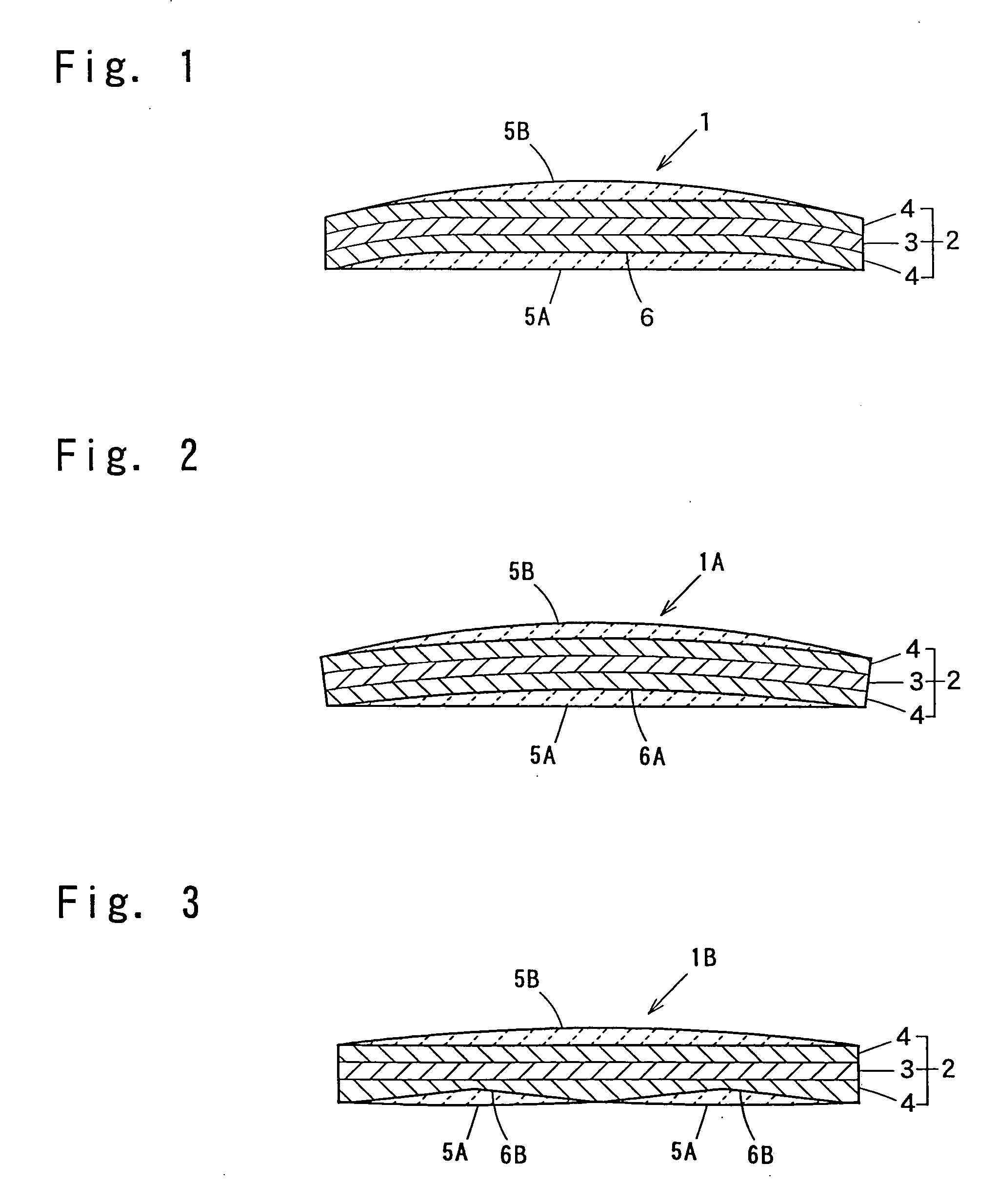

Image

  • Electrode wire material and solar cell having connection lead wire formed of the wire material
  • Electrode wire material and solar cell having connection lead wire formed of the wire material
  • Electrode wire material and solar cell having connection lead wire formed of the wire material

Examples


examples

[0039] A clad material (0.18 mm thick) comprising a middle layer with a thickness of 60 μm composed of Invar (Fe-36.5 mass % Ni) and copper layers with each thickness of 60 μm formed on both faces of the interlayer was prepared. Strip-like materials with each width of 2 mm were produced from the clad material by a slitter and the strip-like materials were further cut into pieces with each length of 40 mm to obtain core materials related to examples. When slitting by the slitter, the intervals of rotary blades were adjusted so as to carry out bending forming in the end parts in the width direction of the each strip-like material to make the transverse cross sectional shape of the core material dish-like as shown in FIG. 1. The cross-sectional shape was observed by an optical microscope (magnification about 200 times) to find that the deepest depth in the recessed part formed in the recessed side of the core material was about 20 μm and the opening width of the recessed part was about...


PUM

PropertyMeasurementUnit
melting pointaaaaaaaaaa
widthaaaaaaaaaa

Abstract

An electrode wire material that can be used in a solar cell is produced without using flattening rolls or endless belts and has excellent solderability. The electrode wire material includes a core material formed of a strip-like conductive material and a hot-dip solder plated layer formed on a surface of the core material. A recessed portion for storing molten solder is formed in the core material along the longitudinal direction and the hot-dip solder plated layer is filled in the recessed portion. The recessed portion for storing molten solder preferably has an opening width in the lateral direction of the core material of about 90% or more of the width of the core material. The core material is preferably formed of a clad material including an interlayer of a low thermal expansion Fe alloy and copper layers formed on both surfaces of the interlayer.

Description

TECHNICAL FIELD [0001] The invention relates to an electrode wire material to be used as a connection lead wire of electronic parts such as solar cells. BACKGROUND ART [0002] Solar cells respectively comprise a semiconductor substrate of a silicon semiconductor having PN junction and connection lead wires soldered to a plurality of front face electrodes formed linearly on the surface of the semiconductor substrate and in general, a plurality of such solar cells are connected in series so as to obtain a desired electromotive force. The series connection is done by connecting connection lead wires soldered to a front electrode of one solar cell to a rear electrode of another solar cell. [0003] The electrode wire material before the connection lead wires being soldered to the front electrode of the semiconductor substrate comprises a core material 51 of a pressed copper wire pressed to be flat by rolling a copper wire halving a circular cross section and hot-dip solder plated layers 52...

Claims


Application Information

Patent Timeline
Patent Type & Authority Applications(United States)
IPC IPC(8): H01L31/00H01L31/04
CPCB23K35/0272B23K35/262B32B15/015Y02E10/50C22C38/08H01L31/0508H01L31/0512C22C13/00H01L31/04H01L31/0224
Inventor SHIOMI, KAZUHIROFUJITA, TOSHIAKIISHIO, MASAAKI
Owner NEOMAX MATERIALS
Learn More