Plasma display panel

a technology of display panel and plasma, which is applied in the direction of discharge tube/lamp details, discharge tube luminescnet screen, address electrode, etc., can solve the problems of low electron heating efficiency and most input voltage consumption, and achieve the effect of enhancing discharge efficiency, preventing the life span of phosphors from being short, and high luminescence efficiency

Inactive Publication Date: 2007-03-22
SAMSUNG SDI CO LTD
View PDF2 Cites 2 Cited by
  • Summary
  • Abstract
  • Description
  • Claims
  • Application Information

AI Technical Summary

Benefits of technology

[0028] According to the above-described plasma display panel of the present embodiments, a uniform electric field can be formed between the sustain electrodes and the scan electrodes by providing floating electrodes so as to correspond to the sustain electrodes and the scan electrodes, respectively. Furthermore, by preventing the bending of lines of electric force established at the edge portions of the sustain and scan electrodes, a sustain discharge can be smoothly performed, thereby enhancing discharge efficiency.
[0029] Furthermore, since an opposed discharge occurs between the sustain electrodes and the scan electrodes, a long-gap discharge is enabled, so that a higher luminescence efficiency can be achieved as compared to the conventional surface discharge structure.
[0030] Furthermore, since the address electrodes are formed on the front substrate, it is possible to prevent the life span of the phosphors from being shortened due to ion sputtering as charges are accumulated on the phosphor layers.

Problems solved by technology

In the cathode sheath region, most of the input voltage is consumed, but the electron heating efficiency is low.

Method used


Image

  • Plasma display panel
  • Plasma display panel
  • Plasma display panel

Examples


first embodiment

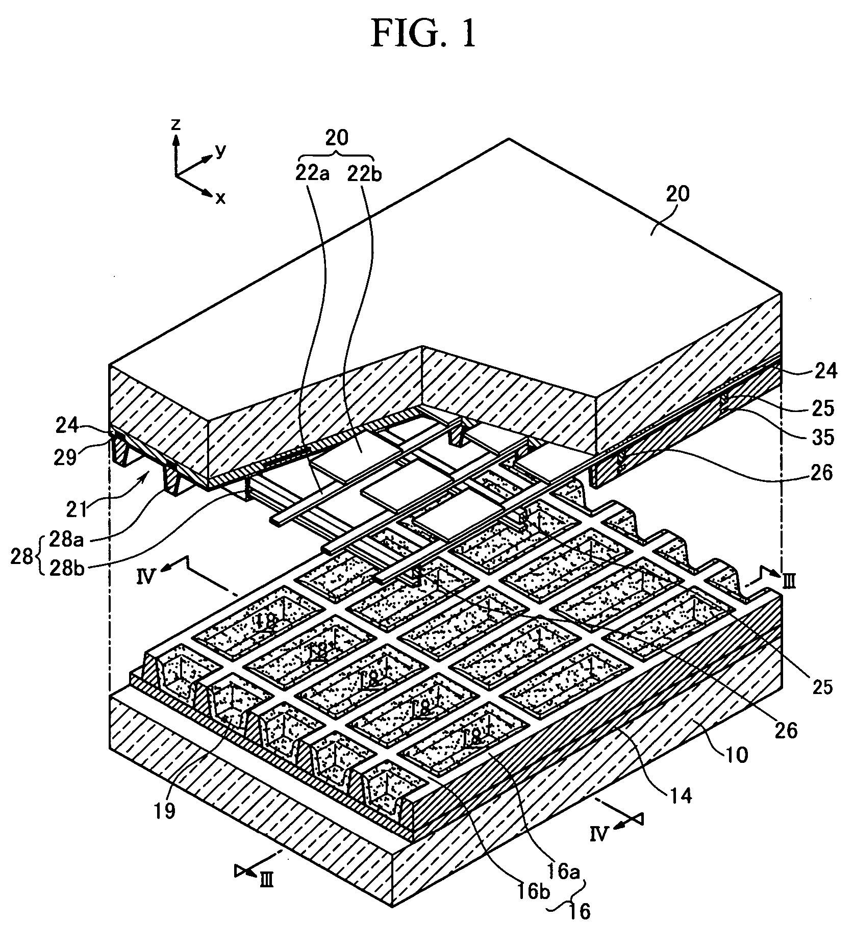
[0039]FIG. 1 is a partial exploded perspective view showing a plasma display panel according to a

[0040] With reference to FIG. 1 to 4, a PDP of the first embodiment includes a first substrate 10 (hereinafter, referred to as a rear substrate) and a second substrate 20 (hereinafter, referred to as a front substrate) arranged to face each other with a predetermined gap therebetween, and a plurality of discharge cells 17 defined between the rear substrate 10 and the front substrate 20. In the discharge cells 17, phosphor layers 19 are formed so as to absorb ultraviolet rays and to emit visible light. Further, a discharge gas (for example, a mixed gas including Xe, Ne, and the like) is filled into the discharge cells 17 so as to generate a plasma discharge.

[0041] Address electrodes 22 are formed on a surface of the front substrate 20 facing the rear substrate 10 to extend along a first direction (hereinafter, referred to as “x-axis direction”). The address electrodes 22 are formed in su...

second embodiment

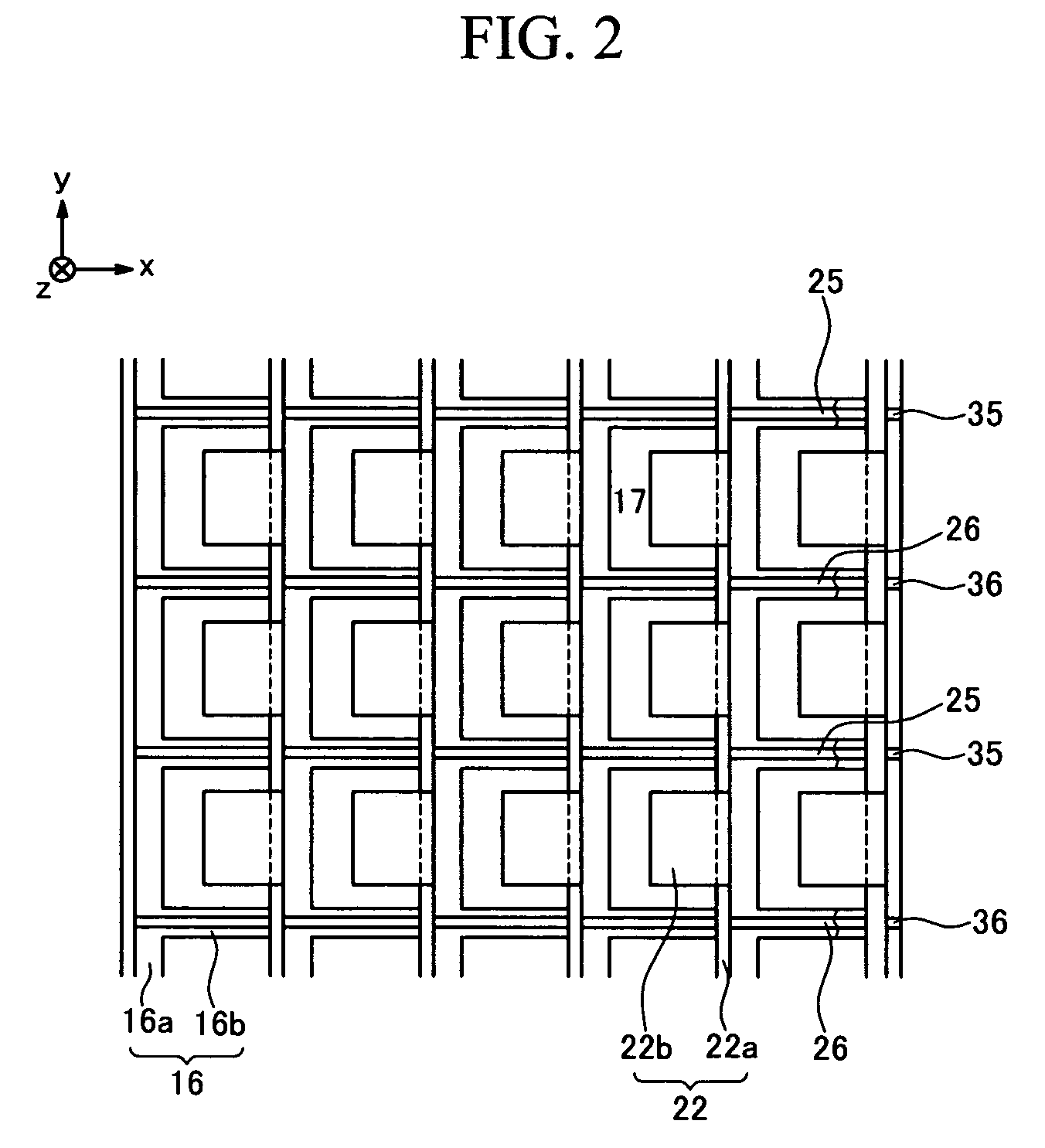
[0071] Referring to FIG. 6, in a plasma display panel first floating electrodes 235 and second floating electrodes 236 are intermittently formed along the second direction (x-axis direction of the drawing). More specifically, the first floating electrodes 235 and the second floating electrodes 236 are formed at portions corresponding to the first discharge spaces 21, but are not formed at portions intersecting the first dielectric layer portion 28a. That is, the first floating electrodes 235 and the second floating electrodes 236 are formed in the first discharge spaces 21 where a discharge is substantially fired. Due to this, an electric field is uniformly formed in the first discharge spaces 21, so the cost of electrode materials can be reduced and the bending of lines of electric force established between the edge portions of the sustain electrodes 25 and the edge portions of the scan electrodes 26 can be efficiently controlled.


PUM


Abstract

A plasma display panel having an opposed discharge structure that can improve discharge efficiency is disclosed. The plasma display panel includes a first substrate and a second substrate arranged to face each other with a predetermined space therebetween, and having a plurality of discharge cells defined in the space between the first and second substrates; phosphor layers formed inside the respective discharge cells; address electrodes formed to extend along a first direction on the second substrate; first and second electrodes formed to extend along a second direction intersecting the first direction, between the first and second substrates and projecting toward the first substrate in a direction away from the second substrate, the first and second electrodes facing each other with a space therebetween; and third and fourth electrodes formed along the second direction between the first substrate and the second substrate, and separated from the respective first and second electrodes in a direction substantially perpendicular to the second substrate.

Description

CROSS-REFERENCE TO RELATED APPLICATION [0001] This application claims priority to and the benefit of Korean Patent Application No. 10-2005-0083672 filed in the Korean Intellectual Property Office on Sep. 08, 2005, the entire content of is are incorporated herein by reference. BACKGROUND OF THE INVENTION [0002] 1. Field of the Invention [0003] The present embodiments relate to a plasma display panel (PDP), and more particularly, to a plasma display panel having an opposed discharge structure that can improve discharge efficiency. [0004] 2. Description of the Related Art [0005] In general, a PDP is a display device that realizes an image using visible light generated by exciting phosphors with vacuum ultraviolet (VUV) rays radiated by plasma obtained by the discharge of a gas. A PDP with a display screen of 60 inches or more can be realized with a thickness of 10 cm or less. Since the PDP is a self-emitting display device like a cathode ray tube (CRT), it provides outstanding color re...

Claims


Application Information

Patent Timeline
Patent Type & Authority Applications(United States)
IPC IPC(8): H01J1/62
CPCH01J11/14H01J11/30H01J11/24H01J11/26H01J11/32H01J2211/265H01J2211/323
Inventor CHO, TAE-SEUNGHWANG, YONG-SHIKYOON, WON-SEOKCHANG, TAE-JUNG
Owner SAMSUNG SDI CO LTD
Why Eureka
Try Eureka