Deep ultraviolet laser apparatus

a laser apparatus and ultraviolet light technology, applied in the direction of laser details, semiconductor lasers, instruments, etc., can solve the problems of difficult to generate laser beams of 190 to 200 nm wavelength regions, and material having sufficient transparency

Inactive Publication Date: 2007-03-22
ADVANCED MASK INSPECTION TECH +1
View PDF6 Cites 21 Cited by
  • Summary
  • Abstract
  • Description
  • Claims
  • Application Information

AI Technical Summary

Benefits of technology

[0015] The present invention has been made in view of the above-described needs involved in the prior art, and an object of the invention is to provide an ultraviolet laser apparatus which can generate efficiently a deep ultraviolet laser beam having a wavelength of about 199 nm.

Problems solved by technology

However, there is such problem that it is difficult to generate a laser beam of 190 to 200 nm wavelength region in simple second harmonic generation (to obtain a twofold frequency, i.e. a half wavelength), or the repetition harmonic generation.
It is also difficult likewise to generate a laser beam in 190 to 200 nm wavelength region in sum-frequency generation by the combination of the wavelengths of a solid laser used commonly.
On one hand, a material having sufficient transparency in the 190 to 200 nm wavelength region is restricted among those having optical nonlinearity; and further there are little crystals satisfying phase matching conditions required for effective wavelength conversion.
In these circumstances, there is also a difficult problem to generate a laser beam in the 190 to 200 nm wavelength region.
In the meantime, it is known that nonlinearity of a nonlinear optical medium in which laser wavelength conversion is effected is in an order of pm / V so that efficient wavelength conversion cannot be made by passing simply a laser beam through the medium.
Accordingly, there is such a problem that a complicated servo system for eliminating the above-described requirement becomes necessary, resulting in a complicated constitution therefor.
Moreover, it has been also pointed out that an optical loss of the outside resonator must be kept to be a small amount.
However, since the manner of using the outside resonator involves the above-described problem, it is difficult to use widely in industrial use application.

Method used


Image

  • Deep ultraviolet laser apparatus
  • Deep ultraviolet laser apparatus

Examples


Embodiment Construction

[0033] In the following, an example of a manner of practice of the deep ultraviolet laser apparatus according to the present invention will be described in detail by referring to the accompanying drawing.

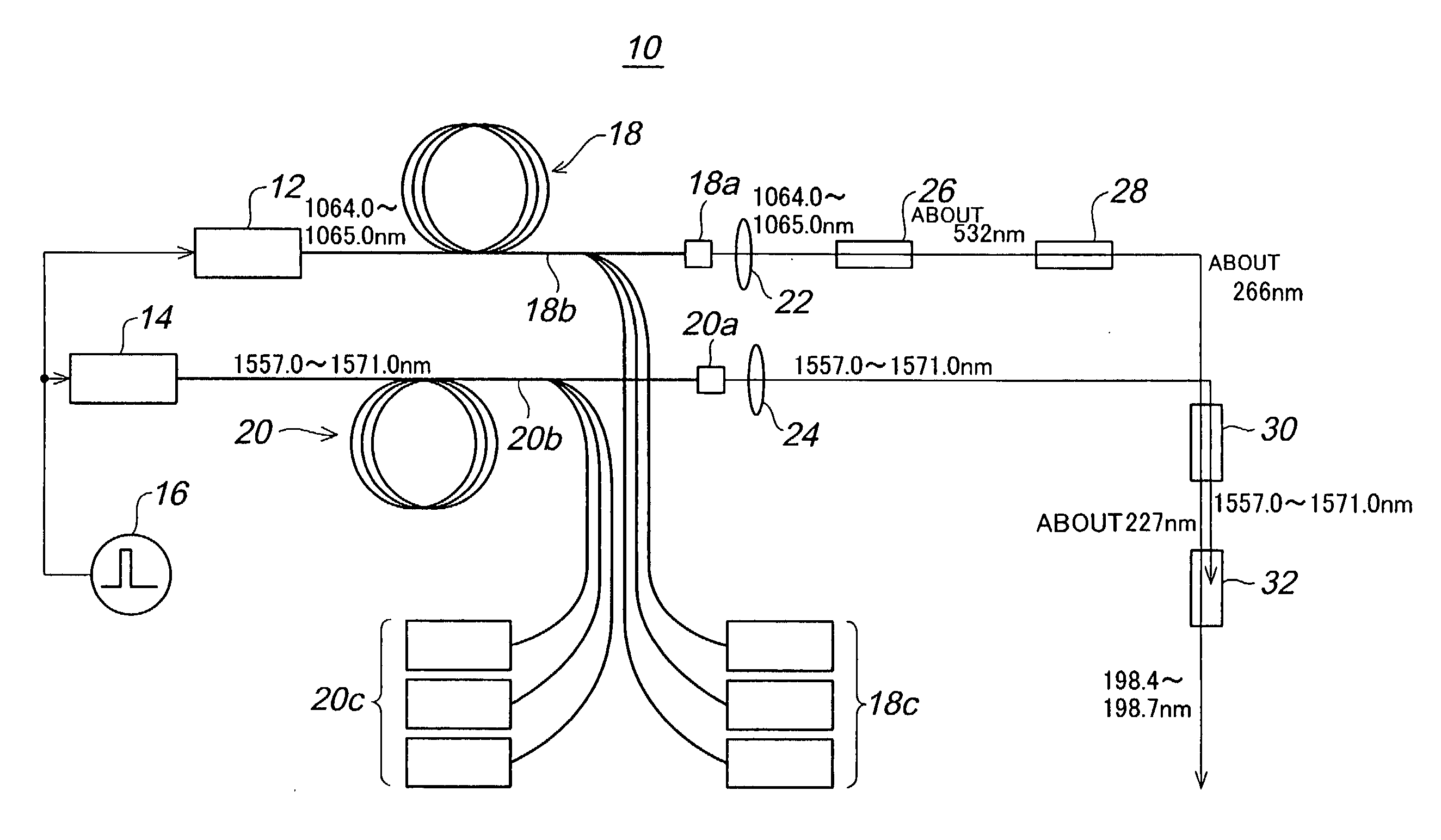
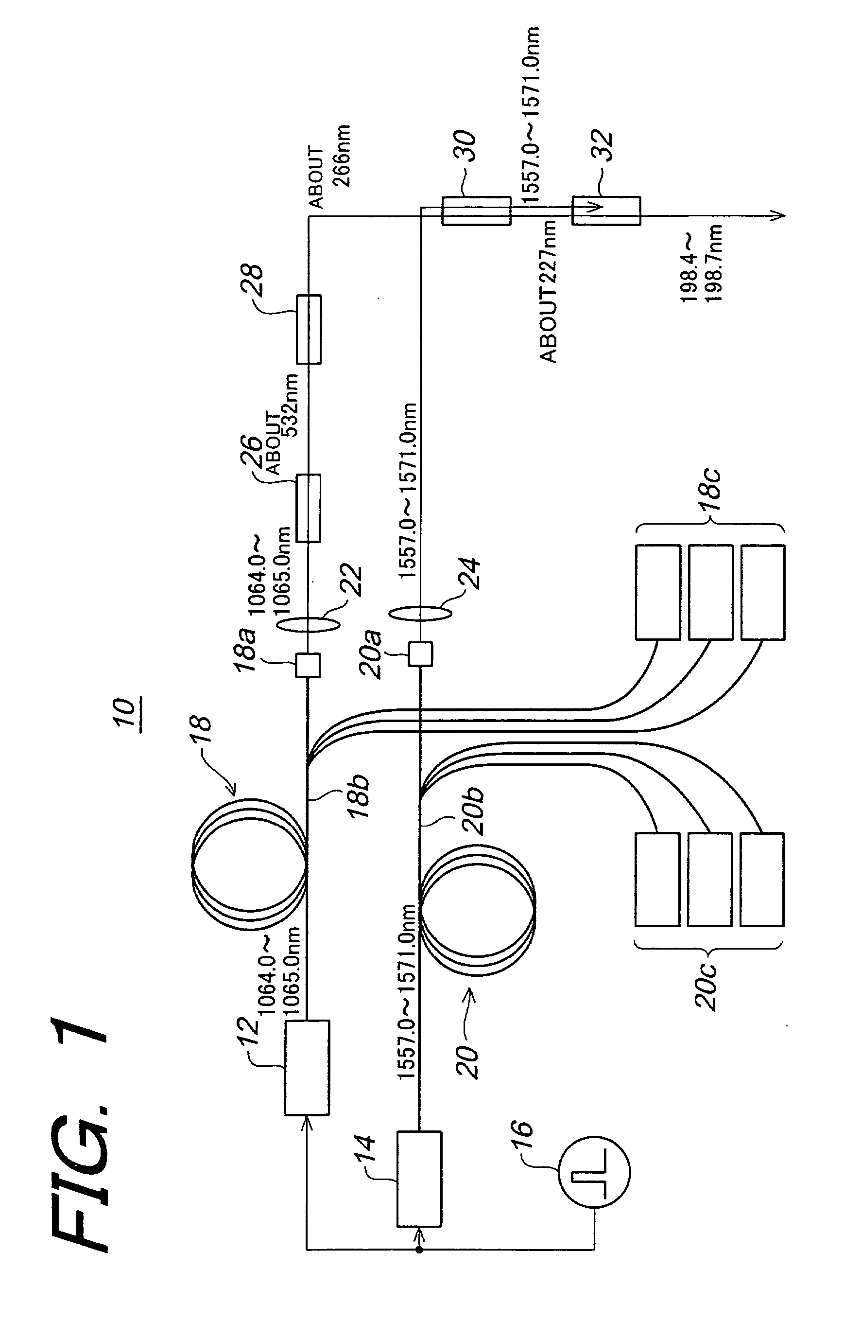
[0034]FIG. 1 is a conceptual constitutional explanatory diagram showing a deep ultraviolet laser apparatus 10 according to an example of a manner of practice of the present invention.

[0035] The deep ultraviolet laser apparatus 10 is composed of a first semiconductor laser 12 for outputting laser beams having 1064.0 to 1065.0 nm wavelengths, a second semiconductor laser 14 for outputting laser beams having 1557.0 to 1571.0 nm wavelengths, a pulse current source 16 for applying a pulsed current for driving the first semiconductor laser 12 and the second semiconductor laser 14, a first optical fiber amplifier 18 for amplifying the laser beam having a wavelength of from 1064.0 to 1065.0 nm output from the first semiconductor laser 12, a second optical fiber amplifier 20 for amplifying...


PUM


Abstract

In order to generate efficiently a deep ultraviolet laser beam having a wavelength in a deep ultraviolet region and to make the generated laser beam to be high output, it is arranged in such that a laser beam having about 227 nm wavelength is generated by sum-frequency mixing of fourth harmonic of the laser beams obtained by amplifying semiconductor laser beams having 1064.0 to 1065.0 nm wavelengths by means of an optical fiber amplifier, and the laser beams obtained by amplifying semiconductor laser beams having 1557.0 to 1571.0 nm wavelengths by means of another optical fiber amplifier; and further laser beams having 198.4 to 198.7 nm wavelengths are generated by sum-frequency mixing of the above sum-frequency mixed laser beam and the above-described semiconductor laser beams having 1557.0 to 1571.0 nm wavelengths.

Description

BACKGROUND OF THE INVENTION [0001] 1. Field of the Invention [0002] The present invention relates to a deep ultraviolet laser apparatus, and more particularly to a deep ultraviolet laser apparatus for generating deep ultraviolet laser beam having wavelengths (ranging from 190 to 270 nm wavelengths) in deep ultraviolet region by utilizing a wavelength conversion technology to which nonlinear optical effects are applied. [0003] 2. Description of the Related Art [0004] In recent years, a variety of deep ultraviolet laser apparatuses for generating deep ultraviolet laser beam are proposed with aiming to apply to a fine processing technology in, for example, electronics industrial fields such as manufacturing processes of semiconductors and the like. [0005] Such conventional deep ultraviolet laser apparatus has been constituted so as to generate a deep ultraviolet laser beam having a target wavelength by the application of the wavelength conversion technology using nonlinear optical effe...

Claims


Application Information

Patent Timeline
Patent Type & Authority Applications(United States)
IPC IPC(8): H01S3/10
CPCG02F1/3532G02F2001/354H01S5/00H01S3/2375H01S3/2383H01S3/06754G02F1/354
Inventor KANEDA, YUSHIURATA, YOSHIHARUWADA, SATOSHIIMAI, SHINICHI
Owner ADVANCED MASK INSPECTION TECH
Why Eureka
Try Eureka