Fuel cell system and method of generating electricity thereby

a fuel cell and electricity generation technology, applied in the direction of fuel cells, fuel cell details, electrical apparatus, etc., can solve the problems of energy loss, inability to use the heat of cathode offgas, and deliberately lowering the temperature of hydrogen to be supplied to the fuel cell, so as to improve the energy efficiency of the fuel cell system

Inactive Publication Date: 2007-03-22
TOYOTA JIDOSHA KK +1
View PDF7 Cites 5 Cited by
  • Summary
  • Abstract
  • Description
  • Claims
  • Application Information

AI Technical Summary

Benefits of technology

[0042] Similarly to the invention above, the hydrogen-containing reformed gas can be generated in reaction of the remaining oxygen, a sufficient amount of the generated water, the cathode offgas having the high-temperature heat energy, and the reforming fuel in the reformer. According to the present invention, it is thus possible to generate electricity by making the most of the high-temperature heat energy of the cathode offgas and improve the energy efficiency of the fuel cell system additionally.

Problems solved by technology

Thus in the conventional fuel cell systems, the temperature of the hydrogen to be supplied to the fuel cell is lowered deliberately, and it is not possible to use the heat of the cathode offgas discharged from the cathode channel of the fuel cell in reaction in the reformer.
In addition, use of the heat exchanger, or the condenser, and the like leads to energy loss and also makes the structure of the fuel cell system more complicated.
It is thus not possible to recover all of the water generated in the electrical power generation in the fuel cell from the cathode channel and to adjust the amount of water supplied to the reformer by using the total amount of water.
The inability to recover all water often results in insufficient supply of water for the reaction in the reformer in conventional fuel cell systems.
Such a phenomenon leads to deterioration in purity of the water in the cathode offgas sent to the reformer, possibly causing a problem of the poisoning of the reforming catalyst in reformer due to adsorption of the vaporized components in proton conductor.

Method used


Image

  • Fuel cell system and method of generating electricity thereby
  • Fuel cell system and method of generating electricity thereby
  • Fuel cell system and method of generating electricity thereby

Examples


example 1

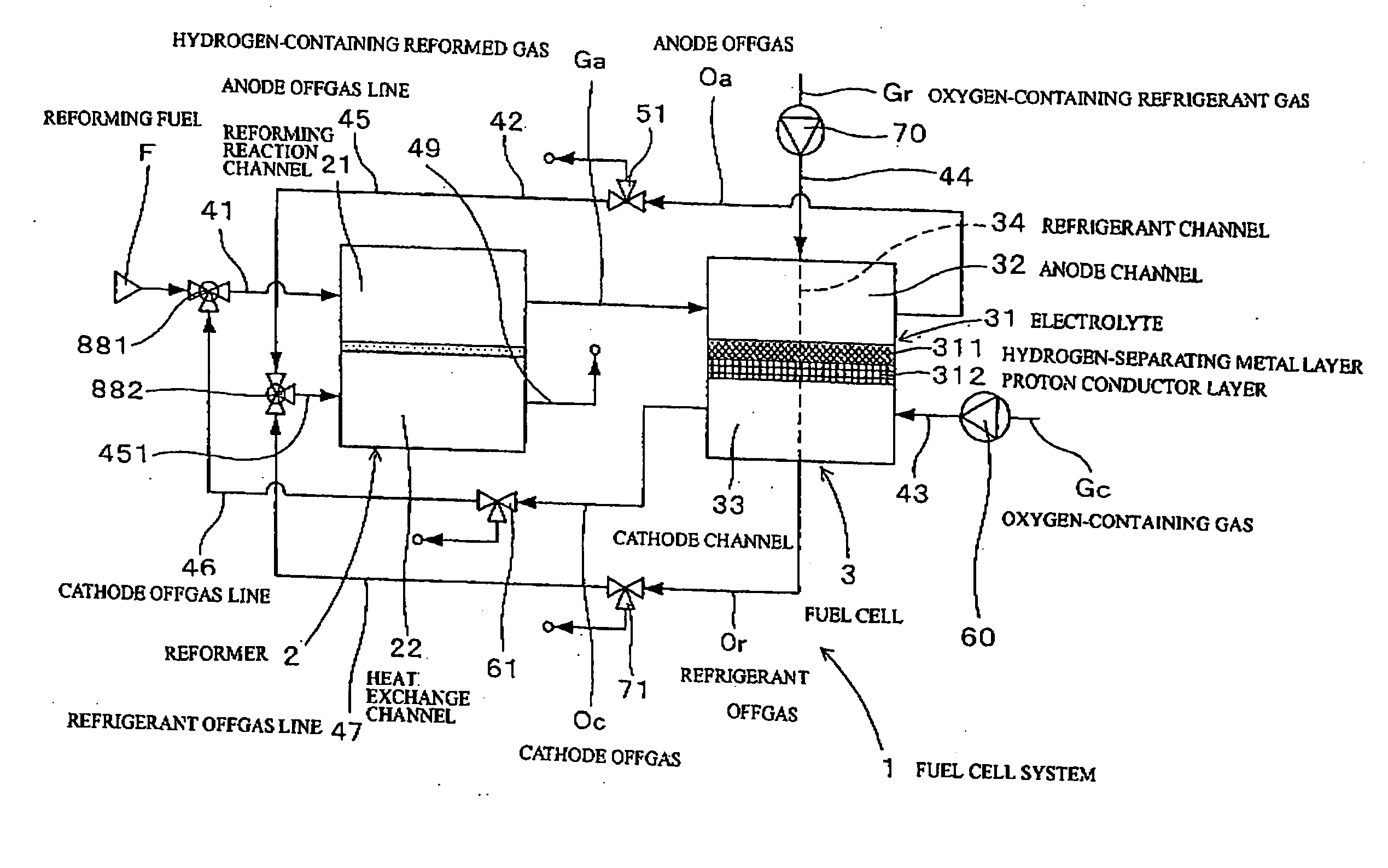
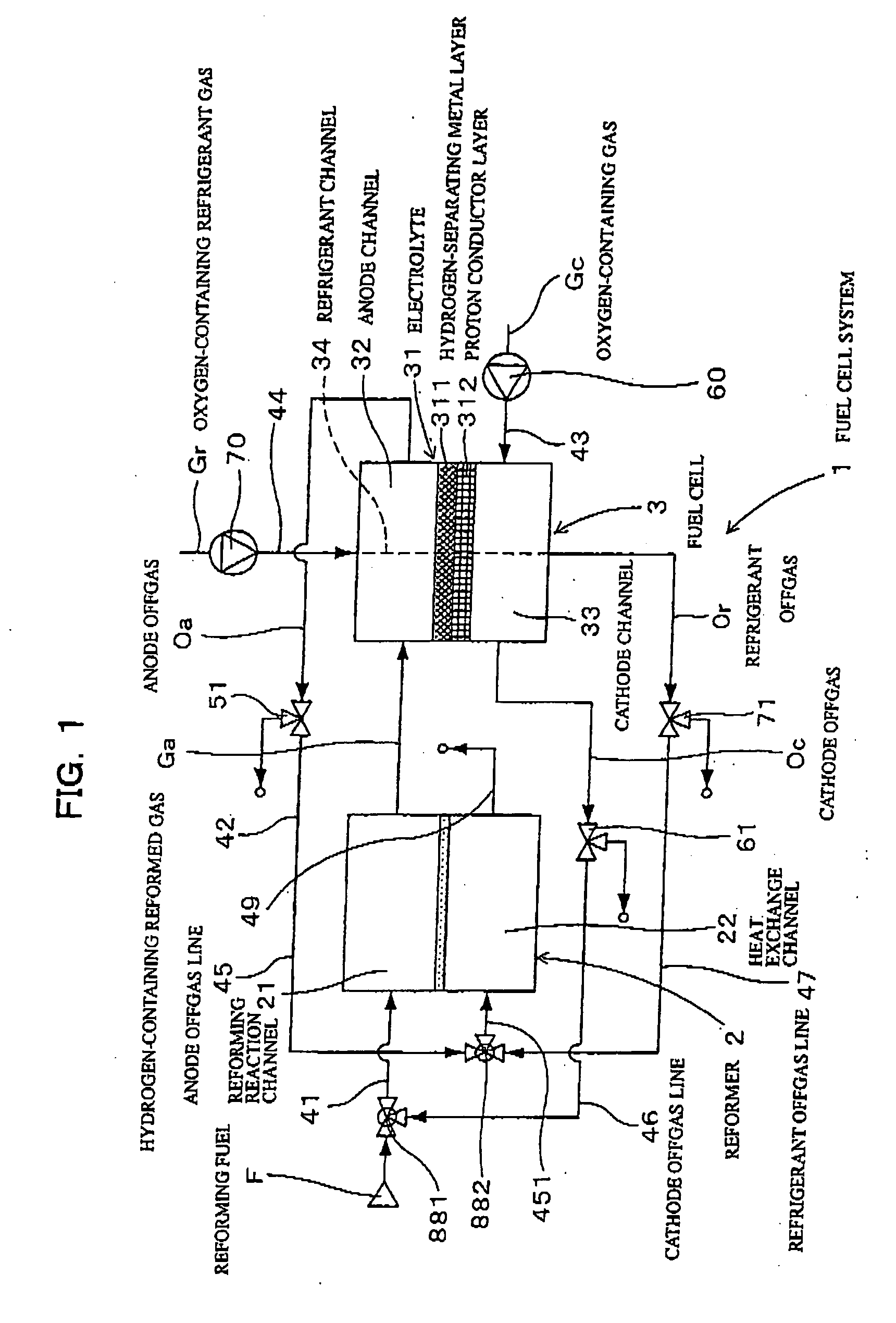
[0142] As shown in FIGS. 1 and 2, the fuel cell system 1 in the present Example has a reformer 2 generating a hydrogen-containing reformed gas Ga containing hydrogen from a reforming fuel F of hydrocarbon fuel and a fuel cell 3 generating electricity by using the hydrogen-containing reformed gas Ga generated in the reformer 2.

[0143] The reformer 2 has a reforming reaction channel 21 generating the hydrogen-containing reformed gas Ga from the reforming fuel F and a heat exchange channel 22 placed close to the reforming reaction channel 21 and heating the reforming reaction channel 21 by combustion.

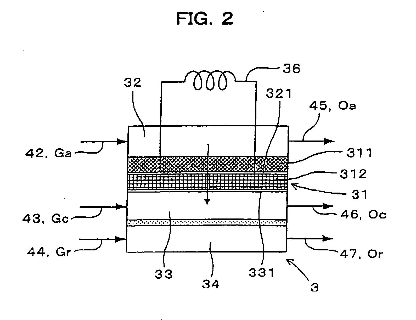
[0144] As shown in FIG. 2, the fuel cell 3 has an anode channel 32 to which the hydrogen-containing reformed gas Ga is supplied from the reforming reaction channel 21, a cathode channel 33 to which an oxygen-containing gas Gc is supplied, an electrolyte 31 installed between the cathode channel 33 and the anode channel 32, and a refrigerant channel 34 to which an oxygen-containing refriger...

example 2

[0214] The present shown in FIGS. 5 to 8 is a variation in which the O / C ratio (oxygen (O) to carbon (C) by mole) and the S / C ratio (water (S) to carbon (C) by mole) in the reforming reaction channel 21 of the reformer 2 are adjusted by installing an oxygen-separating membrane 81 on the cathode offgas line 46 for reducing the oxygen concentration in the cathode offgas Oc.

[0215] The oxygen-separating membrane 81 is formed on the cathode offgas line 46 inside the oxygen-separating membrane device 80. The oxygen-separating membrane device 80 has an oxygen-separating membrane 81 allowing permeation of the oxygen in the cathode offgas Oc and two channels 811 and 812 separated by the oxygen-separating membrane 81. The two channels 811 and 812 are respectively an offgas channel 811 to which the cathode offgas Oc discharged from the cathode channel 33 is fed and an oxygen permeation channel 812 through which oxygen permeated through the oxygen-separating membrane 81 is flowing.

[0216] The ...

example 3

[0234] The Example shown in FIGS. 9 to 11 is another variation in which the O / C and S / C ratios are adjusted by feeding a particular oxygen-containing gas to the cathode offgas line 46 from a unit in the fuel cell system 1 or outside of the fuel cell system 1, for increase in the oxygen concentration in the reforming reaction channel 21.

[0235] In the present Example, the cathode offgas Oc and the particular gas are mixed in the cathode offgas line 46, and the cathode offgas Oc adjusted in oxygen concentration is then fed into the reforming reaction channel 21.

[0236] A cathode offgas three-way regulating valve 61 is also placed on the cathode offgas line 46 in the present Example.

[0237] In yet another variation, the fuel cell system 1 may be configured to mix part of the oxygen-containing refrigerant gas Gr sent to the refrigerant channel 34 with the cathode offgas Oc flowing in the cathode offgas line 46 and send the mixed gas thus obtained to the reforming reaction channel 21, as...


PUM

PropertyMeasurementUnit
temperatureaaaaaaaaaa

Abstract

The fuel cell system 1 has a reformer 2 and a fuel cell 3. The reformer 2 has a reforming reaction channel 21 that generates a hydrogen-containing reformed gas Ga and a heat exchange channel 22 for heating. The fuel cell 3 has an anode channel 32 to which the hydrogen-containing reformed gas Ga is supplied, a cathode channel 33 to which an oxygen-containing gas Gc is supplied, and an electrolyte 31 formed between them. The electrolyte 31 is a laminate of a hydrogen-separating metal layer 311 and a proton conductor layer 312. The fuel cell system 1 has a cathode offgas line 46 for feeding the cathode offgas Oc discharged from the cathode channel 33 to the reforming reaction channel 21.

Description

TECHNICAL FIELD [0001] The present invention relates to a fuel cell system generating electricity by generating a hydrogen-containing reformed gas from a reforming fuel in a reformer and using the hydrogen in the hydrogen-containing reformed gas in a fuel cell. BACKGROUND ART [0002] Fuel cell systems generating electricity by using a reforming fuel such as hydrocarbon or alcohol have a reformer generating a reformed gas containing hydrogen from the reforming fuel, and a hydrogen-separating membrane device separating high-purity hydrogen from the reformed gas, and a fuel cell generating electricity by converting the hydrogen into the proton state and allowing it to react with oxygen. The reformer generates the reformed gas, for example, in steam-reforming reaction of the reforming fuel with water and partial oxidation reaction of the reforming fuel with oxygen. The hydrogen-separating membrane device has a hydrogen-separating membrane for example of palladium, and the hydrogen-separa...

Claims


Application Information

Patent Timeline
Patent Type & Authority Applications(United States)
IPC IPC(8): H01M8/06H01M8/04H01M8/02
CPCH01M8/04022Y02E60/50H01M8/0612H01M8/04097
Inventor SHIMAZU, TAKASHIAOKI, HIROSHIMITSUI, HIROYUKIOGINO, SHIGERUAOYAMA, SATOSHISHIOKAWA, SATOSHIIGUCHI, SATOSHIKIMURA, KENJISATOU, HIROMICHIIZAWA, YASUHIROITO, NAOKIIIJIMA, MASAHIKO
Owner TOYOTA JIDOSHA KK
Why Eureka
Try Eureka