Composite porous body, gas diffusion layer member, cell member, and manufacturing method thereof

a technology of gas diffusion layer and porous body, which is applied in the direction of sustainable manufacturing/processing, cell components, and separation processes, etc., can solve the problems of conductive porous body disadvantage, volume, weight, cost and the like, and ensure the handling of conductive porous bodies, and achieve simple configuration, improved effective use area, and guaranteed handling

Active Publication Date: 2007-03-22
MITSUBISHI MATERIALS CORP
View PDF5 Cites 27 Cited by
  • Summary
  • Abstract
  • Description
  • Claims
  • Application Information

AI Technical Summary

Benefits of technology

[0017] The invention has been achieved in consideration of the foregoing problems. It is therefore an object of the invention to provide a composite porous body and a manufacturing method thereof that handleability of a conductive porous body is ensured while its effective use area is improved, to realize a fuel cell which can be simply configured, can be made small-sized, can be easily manufactured, and can supply power efficiently, and to provide a cell member which is excellent in productivity and enables a fuel cell to be made small-sized and lightweight.

Problems solved by technology

However, since these types of conductive porous bodies generally have properties of low-strength and easy deformation, difficulties in handling of the conductive porous bodies such as a difficulty in incorporating the conductive porous bodies into apparatuses have conventionally been indicated.
For this reason, this is disadvantageous in volume, weight, cost and the like.
Therefore, the effective use area of the conductive porous body is inevitably reduced.
Accordingly, new problems have occurred in that desired functions in the above use of the conductive porous body may deteriorate, or the size of the conductive porous body may be made large for supplementing such a reduced number of pores of the conductive porous body.
Thus, if holes for fixation to an apparatus are bored in the reinforcing portion, there is a problem that it is difficult to realize high-precision working, for example, a problem that a cut end of the conductive porous body is exposed to inner peripheral edges of the holes.
In this case, a problem also occurs in that the volume and weight of the separator plate required to have a certain degree of thickness for the grooves hinder that a fuel cell is made small-sized and lightweight.
Moreover, since the conductive porous body, such as a carbon sheet, constituting the gas diffusion layer, has properties of low strength and easy deformation, there is a problem in that its handling is difficult, which may result in a difficulty in manufacturing fuel cells.
Therefore, the manufacture of the flat fuel cell is not easy.
When the fuel cell is intended to be made smaller, it is difficult to surely fill a sealing agent into a minute gap between unit cells having a multi-layered structure.
Thus, there is a fear that problems such as poor insulation between the unit cells and leakage of fluid fuel due to insufficient filling of the sealing agent may be caused.
Moreover, in the configuration described in Patent Document 4, since the conductive porous body, such as a carbon sheet, constituting the gas diffusion layer, has properties of low strength and easy deformation, there is a problem in that its handling is difficult, which may result in a difficulty in manufacturing fuel cells.
Further, since a methanol aqueous solution as fuel or air is required to be fed through the stacked narrow fluid channels and thus an auxiliary mechanism such as a pump is required, this is disadvantageous in volume, weight, cost and the like.

Method used


Image

  • Composite porous body, gas diffusion layer member, cell member, and manufacturing method thereof
  • Composite porous body, gas diffusion layer member, cell member, and manufacturing method thereof
  • Composite porous body, gas diffusion layer member, cell member, and manufacturing method thereof

Examples


example 1

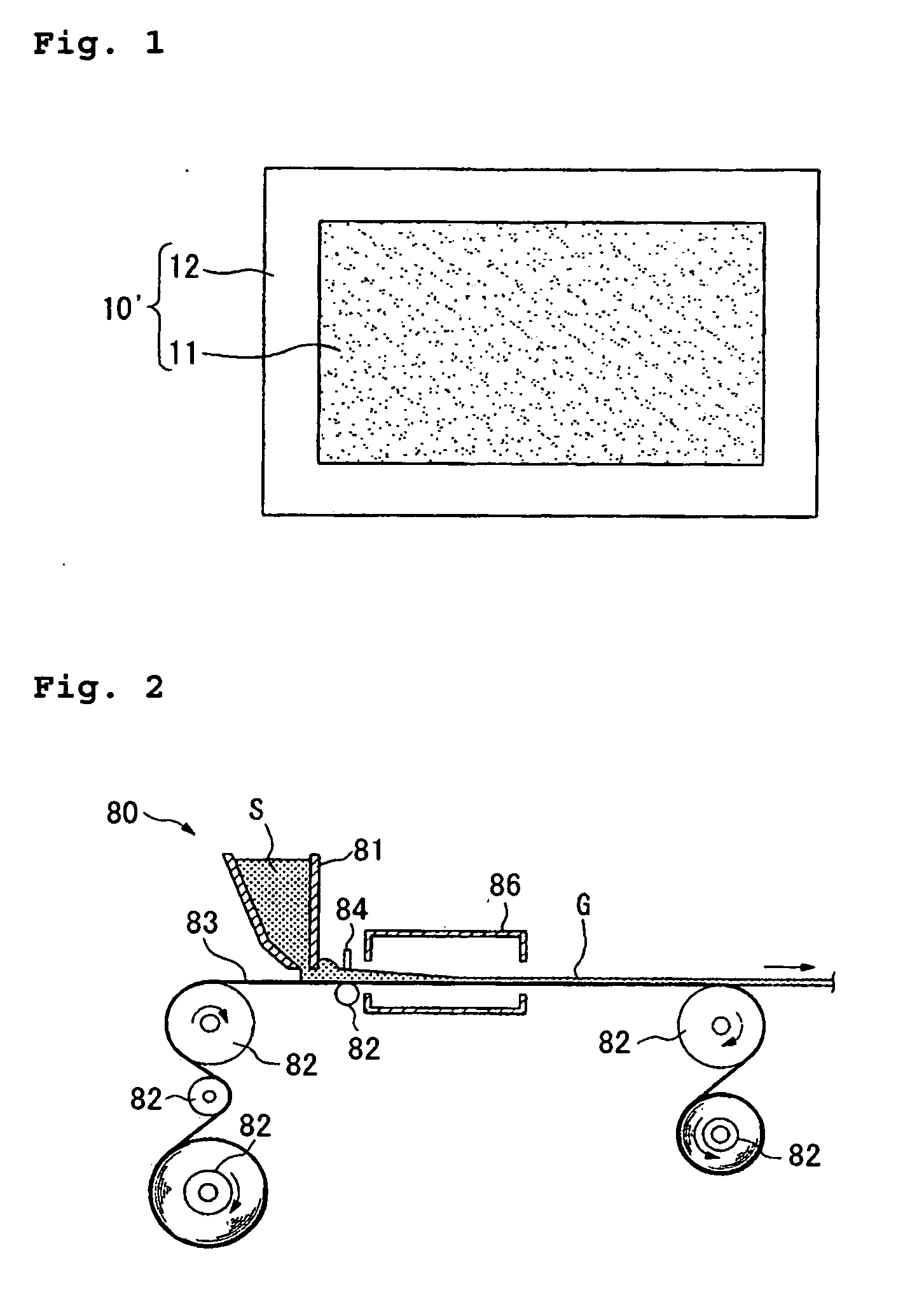
[0165] As shown in FIG. 1, a composite porous body 10′ according to the invention includes a sheet-like conductive porous body 11 and a resin portion 12 extending in the in-plane direction of the conductive porous body 11, which are integrally formed in the shape of a rectangular thin plate.

[0166] The conductive porous body 11 is a rectangular thin plate having a three-dimensional mesh structure, has air permeability and a water absorption property by virtue of mutual communication between laterally opened pores in various directions, and has features that are lightweight and large in surface area. In addition, the conductive porous body 11 may be made of metals, carbon substances containing crystalline graphite or non-crystalline amorphous carbons, and further metallic non-woven fabrics.

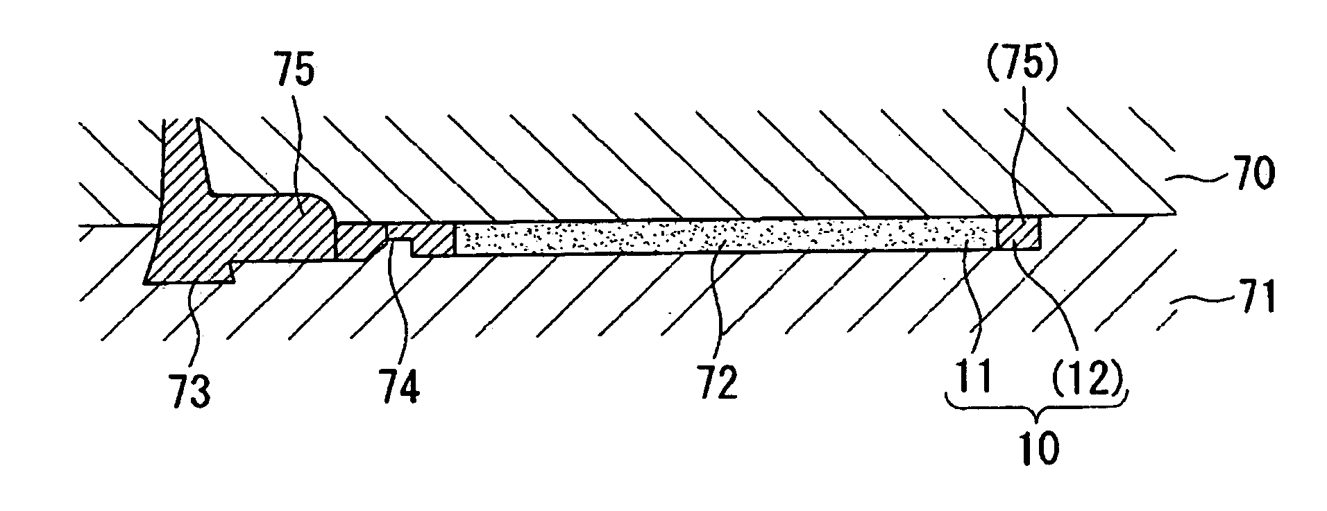
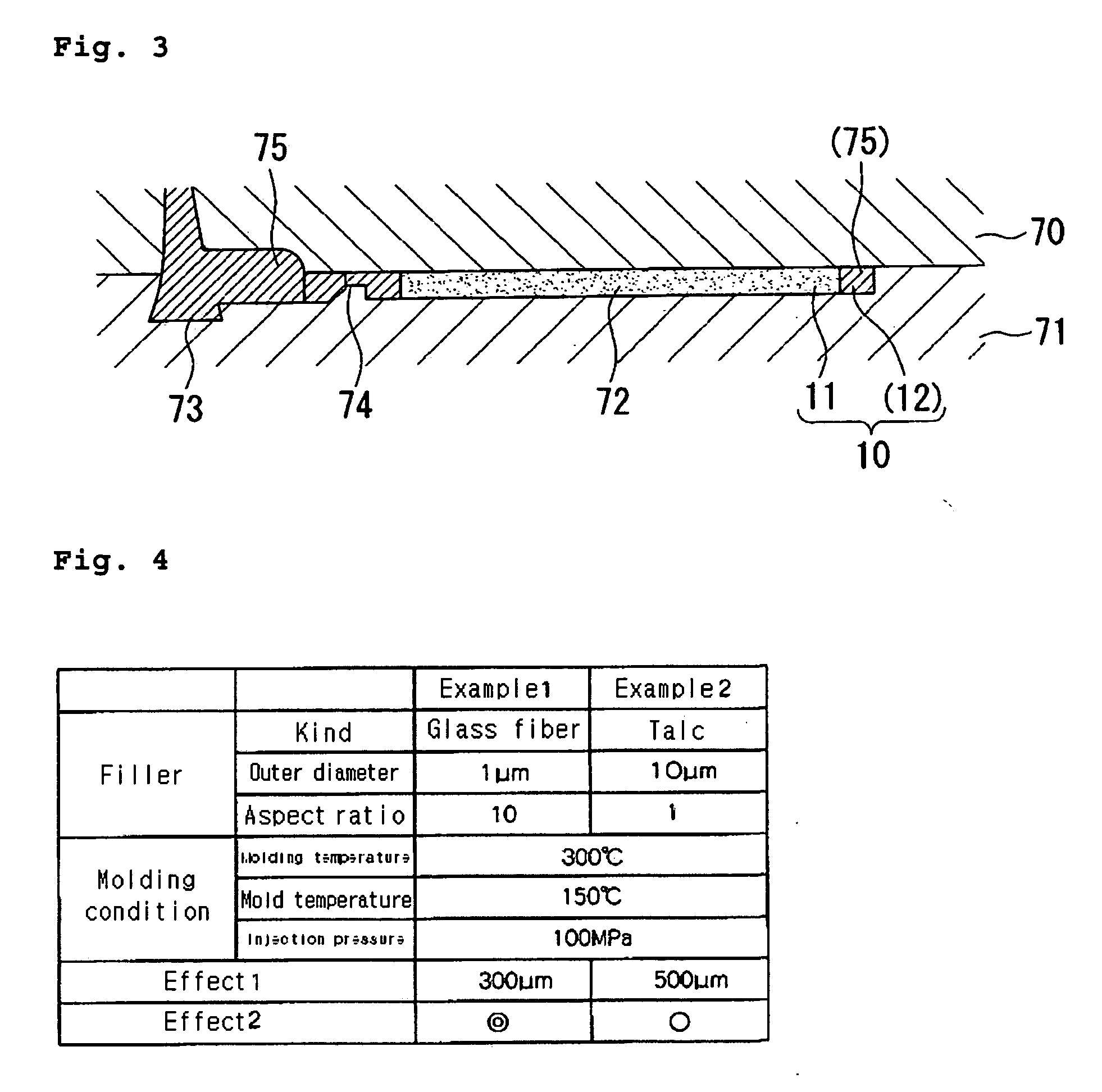
[0167] The resin portion 12 is formed in the shape of a thin plate connected to an outer peripheral edge of the conductive porous body 11 and is formed with almost the same thickness as the conduc...

example 2

[0188]FIG. 5 shows a gas diffusion layer member 10 according to Example 2 of the invention. The gas diffusion layer member 10 includes sheet-like conductive porous bodies 11, terminal tabs 2 protruding from the conductive porous bodies 11, and a resin frame 13 provided so as to surround the peripheries of the conductive porous bodies 11. An end 2a of each terminal tab 2 is adapted to be exposed to an outer face 13a of the resin frame 13.

[0189] Since the gas diffusion layer member 10 causes electrons collected in the conductive porous body 11 to flow out from the terminal tab 2, or causes electrons flowing in from the terminal tab 2 to flow out into conductive porous body 11, the conductive porous body 11 and the terminal tab 2 are formed of a material having excellent electrical conductivity. In addition, when corrosion is problematic, a corrosion-resistant material such as stainless steel is preferably used.

[0190] In the embodiment of the gas diffusion layer member 10 shown in FI...

example 3

[0219] As shown in FIGS. 15 and 16, each of the gas diffusion layer members 10 and 20 according to Example 3 of the invention is a rectangular thin plate-like member in which a gas diffusion electrode 11 or 21 made of a sheet-like conductive porous body and a resin portion 12 or 22 extending in the in-plane direction to cover the periphery of the gas diffusion electrode 11 or 21 are integrally formed with each other.

[0220] The cross-sections of principal parts of a polymer electrolyte fuel cell 100 of the invention including the gas diffusion layer members 10 and 20 are shown in FIGS. 17 and 18.

[0221] The polymer electrolyte fuel cell 100 adopts a stacked structure in which unit cells 130 each having the gas diffusion layer members 10 and 20 and an electrolyte layer 121 are stacked with separator plates 122, 123 and 124 disposed therebetween between. In addition, FIG. 17 is a cross-sectional view taken along a line III-III shown in the gas diffusion layer member 10 of FIG. 15, and...


PUM

PropertyMeasurementUnit
aspect ratioaaaaaaaaaa
outer diameteraaaaaaaaaa

Abstract

A composite porous body, a gas diffusion layer member of a polymer electrolyte fuel cell, a cell member for the polymer electrolyte fuel cell, and manufacturing methods thereof are provided. The composite porous body is a metallic composite porous body in which a sheet-like metal portion composed of a composite porous body having a three-dimensional mesh structure and a resin portion extending in an in-plane direction of the metal portion are integrally formed with each other. The gas diffusion layer member of a polymer electrolyte fuel cell is composed of a composite porous body in which a sheet-like metal portion composed of a composite porous body having a three-dimensional mesh structure and a resin portion extending in an in-plane direction of the metal portion are integrally formed with each other. Also, the gas diffusion layer member of a polymer electrolyte fuel cell has a separator plate, and the conductive porous body placed on at least one surface of the separator plate. A resin frame is integrally provided so as to cover the peripheries of separator plate and the conductive porous body.

Description

BACKGROUND OF THE INVENTION [0001] 1. Field of the Invention [0002] The present invention relates to a composite porous body, a gas diffusion layer member of a polymer electrolyte fuel cell, a cell member for the polymer electrolyte fuel cell, and manufacturing methods thereof. [0003] 2. Description of the Related Art [0004] Sheet-like conductive porous bodies having a three-dimensional mesh structure are applied to various kinds of use, such as filters, heat-radiating members, water-absorbing members, and gas diffusion layer members for polymer electrolyte fuel cells and are provided in various apparatuses. However, since these types of conductive porous bodies generally have properties of low-strength and easy deformation, difficulties in handling of the conductive porous bodies such as a difficulty in incorporating the conductive porous bodies into apparatuses have conventionally been indicated. As means for solving this problem, there has been known, for example, a configuration...

Claims


Application Information

Patent Timeline
Patent Type & Authority Applications(United States)
IPC IPC(8): H01M4/94H01M8/02H01M8/10H01M4/88B32B3/06B32B5/24B01D39/12B29C45/14
CPCB01D39/12B29C45/14336B29K2105/04H01M8/0232H01M8/0234H01M8/0241Y02E60/50H01M8/0282H01M8/0284H01M8/0286H01M8/1011H01M8/242H01M2008/1095H01M8/0273H01M8/2418H01M8/2483Y10T428/249955Y10T428/249962Y02P70/50
Inventor WADA, MASAHIROKANDA, EIKOISOBE, TAKESHIKATO, KOMEISHIBUYA, TAKUMIAKIYAMA, SAKAEHAMADA, KAZUICHI
Owner MITSUBISHI MATERIALS CORP
Why Eureka
Try Eureka