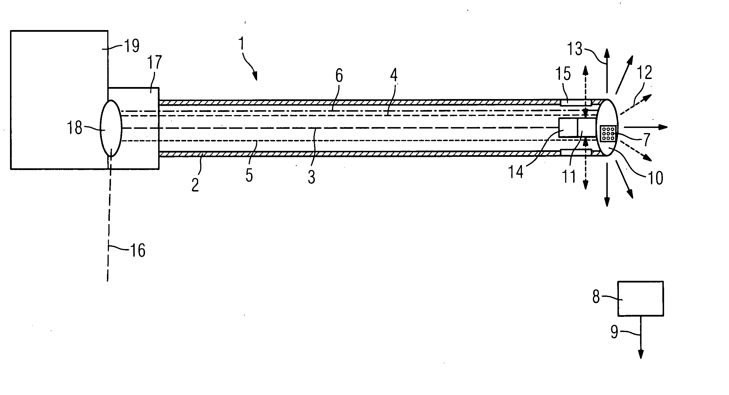
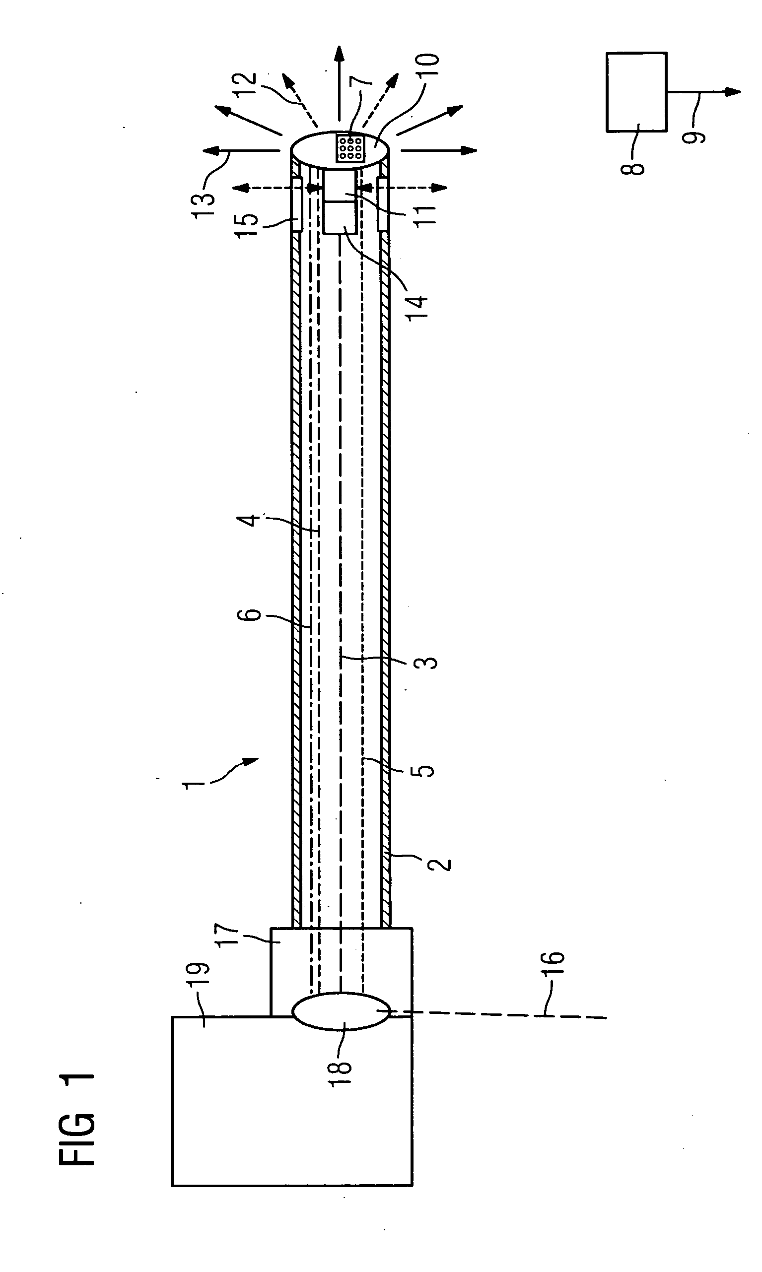
[0052]FIG. 1 shows an inventive catheter device 1 with a laser angioplasty catheter. The inventive catheter device 1 features a hollow flexible drive shaft 2 in which an OCT signal line 3 and an IVUS signal line 4 are integrated. The OCT signal line 3 is embodied as a glass fiber line in this case. In addition a signal line 5 of the position sensor system which is embodied as an electromagnetic sensor system, and a signal line 6 for the laser energy for performing the laser angioplasty are arranged in the flexible drive shaft 2, with said lines being optical fibers. Thus the surrounding drive shaft 2 produces an integrated unit and which embodies a combination catheter which replaces previously used separate catheters, with the benefit of better image monitoring and treatment of vessel blockages.
[0053] A preferred embodiment is an embodiment not shown here in which the drive shaft 2 does not rotate but only the IVUS and the OCT sensor, in order where necessary to avoid friction between the catheter device and the inner wall of the vessel and at the same time effect a rotation of an OCT sensor.
[0054] The signal line 5 of the electromagnetic position sensor system leads to antennas 7 arranged at the tip of the catheter device 1, which are arranged in the x, y and z direction and which are merely shown schematically here. The antennas 7 interact with an emitter and/or receiver system 8 outside the body, which in its turn features position sensors or detectors. From here the data, as indicated by the arrow 9, is forwarded via a corresponding interface to a position detection unit.
[0055] A lens 10 for emitting laser light or laser energy, which is used for the treatment of the vessel blockage, is activated via the signal line 6. The lens 10 is embodied to be partly transparent for ultrasound in this case so that the ultrasound signals of an IVUS sensor 11, which are indicated here by dashed arrows 12, can penetrate the lens 10. The lens 10 emits the energy forwards or sideways, as shown here by the arrows 13.
[0056] An OCT sensor 14 connected to the OCT signal line 3 is embodied as a rotating mirror, whereby the OCT sensor 14 as well as the IVUS sensor 11 is arranged in the direction of advance of the catheter device 1 behind the lens 10. A transparent exit window 15 of the surrounding drive shaft 2 is provided in the area of the OCT sensor 14 or of the IVUS sensor 11 through which the infra-red light and ultrasound to make the imaging possible can emerge. The OCT sensor can, in an alternative not shown here, also be embodied as a rotating shaft on which a light exit or light entry windows present.
[0057] In the rear area of the catheter device 1 there is additionally a connection 16 for introducing a contrast means and/or flushing fluid. Operation of the catheter device 1 is made possible via a mechanical connection system 17 and a rotation coupling 18 for the connections. The catheter device 1 can in this case be advanced and withdrawn while a rotational movement for example of the OCT sensor is occurring. Finally the signal and/or drive unit 19 is connected downstream which is used to create the movement as well as to generate signals and detect signals.
[0058] Thus a laser angioplasty treatment of a vessel blockage can be undertaken with the inventive combination catheter using optimum image monitoring by OCT and IVUS in combination with electromagnetic position sensors.
[0059]FIG. 2 shows an inventive catheter device 20 with a pincer-type CTO catheter. Here, in addition to a tubular catheter shell 21, a hollow flexible drive shaft 22 is again provided in the inner area of the catheter shell 21 in which an OCT signal line 23 as well as an IVUS signal line 24 are integrated. Signal lines 23 or 24 lead to an OCT sensor 25 which is embodied as a mirror, and to an IVUS sensor 26 arranged before it in the direction of the treatment to be performed. The catheter shell 21 features a transparent window ring 27 in its front area through which the light or ultrasound of the OCT sensor 25 and of the IVUS sensor 26 can escape.
[0060] For treatment of the complete vessel blockage “pincers”28 are arranged at the tip of the catheter device 20 with which the plaque in the vessels can be pushed away piece-by-piece, in order to remove the complete vessel blockage in stages. In the rear area of the catheter device 20 is a mechanical device 29 for actuating the “pincers”28 of the pincer-type catheter. In addition there is again a connection 30 for bringing in contrast media and/or flushing fluid, and also a rotation coupling 31 and a mechanical connection system 32. The imaging catheter is activated via a signal and/or drive unit 33. The recorded image signals are additionally fed back to the signal and/or drive unit 33 via the signal lines 23, 24 for further processing in order to create image recordings from them. The position sensor system also present is not shown here for reasons of clarity.
[0061]FIG. 3A shows an inventive catheter device 34 with a pincer-type CTO catheter which features an opening for transmission of the OCT and IVUS sensors in its tip area. The catheter device 34 is activated via a signal and/or drive unit 35 which enables imaging operation. As well as a connection 36 for bringing in contrast media and/or flushing fluid, a mechanical connection system 37 for connection with the front part of the catheter device 34 and a rotation coupling 38 for the connections of the catheter device 34 are provided.
[0062] A hollow flexible drive shaft 40 is arranged in a catheter shell 39 in which the IVUS signal line 41 and the OCT signal line 42 are routed. A “pincer”45 for dissolving the constriction of the vessel can be operated via a mechanical device with corresponding lines 44. The “pincer”45 features an opening 46 through which an OCT sensor 47 and an IVUS sensor 48 can be moved, in order to record image data in advance of the “pincers”45. In the arrangement of the OCT sensor 47 or of the IVUS sensor 48 images can also be recorded here via a corresponding transparent embodiment of the catheter shell 39. Thus the area for treatment can be recorded over a wide area and thereby the treatment or the progress of the treatment better assessed.
[0063]FIG. 3B shows a front view of the tip of the catheter device 34, in which an upper half 49 and a lower half 50 of the “pincers”45 can be seen. The opening 46 is shown in the central area, through which the sensors 47 and 48 can move to record image data.
[0064]FIG. 4A finally shows an inventive device 51 with a high-frequency-based CTO catheter. The catheter device 51 again features a drive shaft 52 in which the glass fiber line for the OCT sensor as well the lines for the IVUS sensor the electromagnetic position sensor system and the optical fiber for activation of a coil 53 not shown in the drawing are accommodated. An emission of high-frequency energy is possible via the coil 53 in order to remove plaque in the vessel by this method. In the front area of the coil 53 an OCT sensor 54 is arranged, with an IVUS sensor 55 in front of it. In addition an antenna system 56 of the electromagnetic position sensor system is indicated. A vessel blockage can be rectified with the inventive catheter device 51 by emitting high-frequency radiation by means of the coil 53.
[0065]FIG. 4B shows an inventive catheter device 51b with a high-frequency-based CTO catheter and a rotatable OCT and IVUS catheter. The catheter device 51b features a flexible catheter shell 52b which is embodied in a fixed position. A coil 53b allows the emission of high-frequency radiation for plaque removal. In front of the coil 53b an IVUS sensor 55b is initially arranged, in front of which an OCT sensor 54b is connected. The OCT sensor54b and the IVUS sensor 55b are controlled via the signal lines 52c which are shown in simplified form in this figure. Furthermore an antenna system 56b is again provided for a position sensor system.
[0066] The difference from the device depicted in FIG. 4A is that here the catheter shell 52b is not embodied as a rotating drive shaft but that the OCT and the IVUS catheters with their sensors 55b and 54b rotate within the catheter shell 52b, as shown by the arrows in the diagram. This enables damage to the vessel wall in critical areas of the vessel to be avoided, since the rotating section of the catheter device 51b can no longer come into direct contact with the vessel wall.
[0067]FIG. 5 shows an inventive x-ray device 57 with a CTO catheter device, which is based on sending out high-frequency radiation. A patient not shown in this diagram is supported on a patient table 58 for treatment and radiation is emitted via a radiation source 59 in the direction of the patient table 58. The radiation is produced via a high-voltage generator 61 controlled via a system control 62. Opposite a radiation source 59 an x-ray detector 60 is arranged, which is connected in its turn with a preprocessing unit 63 for x-ray images. In addition a connection 64 is provided for physiological sensors, which is coupled to a physiological signal processing 65 in order to control ECG signals or pulse signals or the breathing and the blood pressure of a patient.
[0068] A connection 66 is made via a terminal for the CTO catheter to a signal interface 67 for the actual treatment by OCT, IVUS and the electromagnetic position sensor system. In addition there is a connection for connecting a high-frequency based CTO catheter device 68 and a data bus 69. Another version of the CTO catheter device is alternately possible. There are also preprocessing units 70 to 72 for the OCT images, the IVUS images and the electromagnetic position sensor system provided. The associated image processing units 73, 74 and 75 are also connected to the data bus 69. The power is supplied via a power supply unit 76. Furthermore an image processing unit 77 for the x-ray images is connected to the data bus 69, which features a connection to an image data store 78 for archiving and storing the recorded images. A calibration unit 79 as well as an image correction unit 80 enables interference fields or artifacts of the imaging to be taken into account. The images are fused and reconstructed in an image fusion and/or reconstruction unit 81. In addition there is an interface 82 to patient data or image data system.
[0069] The image data obtained from OCT, IVUS and the position sensor system as well as the x-ray images and possible fusion images of the different imaging techniques are shown on a display unit 83 in two dimensions, three dimensions or four dimensions. The display unit 83 is connected to an input 84 for input by a user.
[0070]FIG. 6 shows a sketch or sensor readout during execution of an inventive method with the x-ray device 57 of FIG. 5. In this case the sensors of the x-ray device 57 are read out with a partial time offset and clocked. Firstly a system clock is predefined by creating individual system pulses with the pulse generation being followed by the switching of the x-ray radiation and the activation of the magnetic location. After the x-ray radiation is switched of the x-ray detector readout occurs and at the same time the IVUS data is read out. Subsequently the OCT data is read out, with this occurring at the same time as the readout of the ECG and the data for respiration. During the readout of the IVUS data and of the x-ray detector the high-frequency energy which is being emitted to remove the vessel blockage is active. This means that the individual sensor is read out or the components of the catheter device are activated in such a way that a mutual fault can be excluded. The time-offset and clocked readout shown here is to be seen as an example for a readout avoiding interference influences.