Control system and control method for cogeneration system

Inactive Publication Date: 2007-03-29
HITACHI LTD
View PDF7 Cites 25 Cited by
  • Summary
  • Abstract
  • Description
  • Claims
  • Application Information

AI Technical Summary

Benefits of technology

[0009] The Patent Document 1 discloses the technique wherein some of the cogeneration systems for household use installed at customers of the electric power network are operated at high power, a

Problems solved by technology

This may deteriorate the

Method used


Image

  • Control system and control method for cogeneration system
  • Control system and control method for cogeneration system
  • Control system and control method for cogeneration system

Examples


embodiment 1

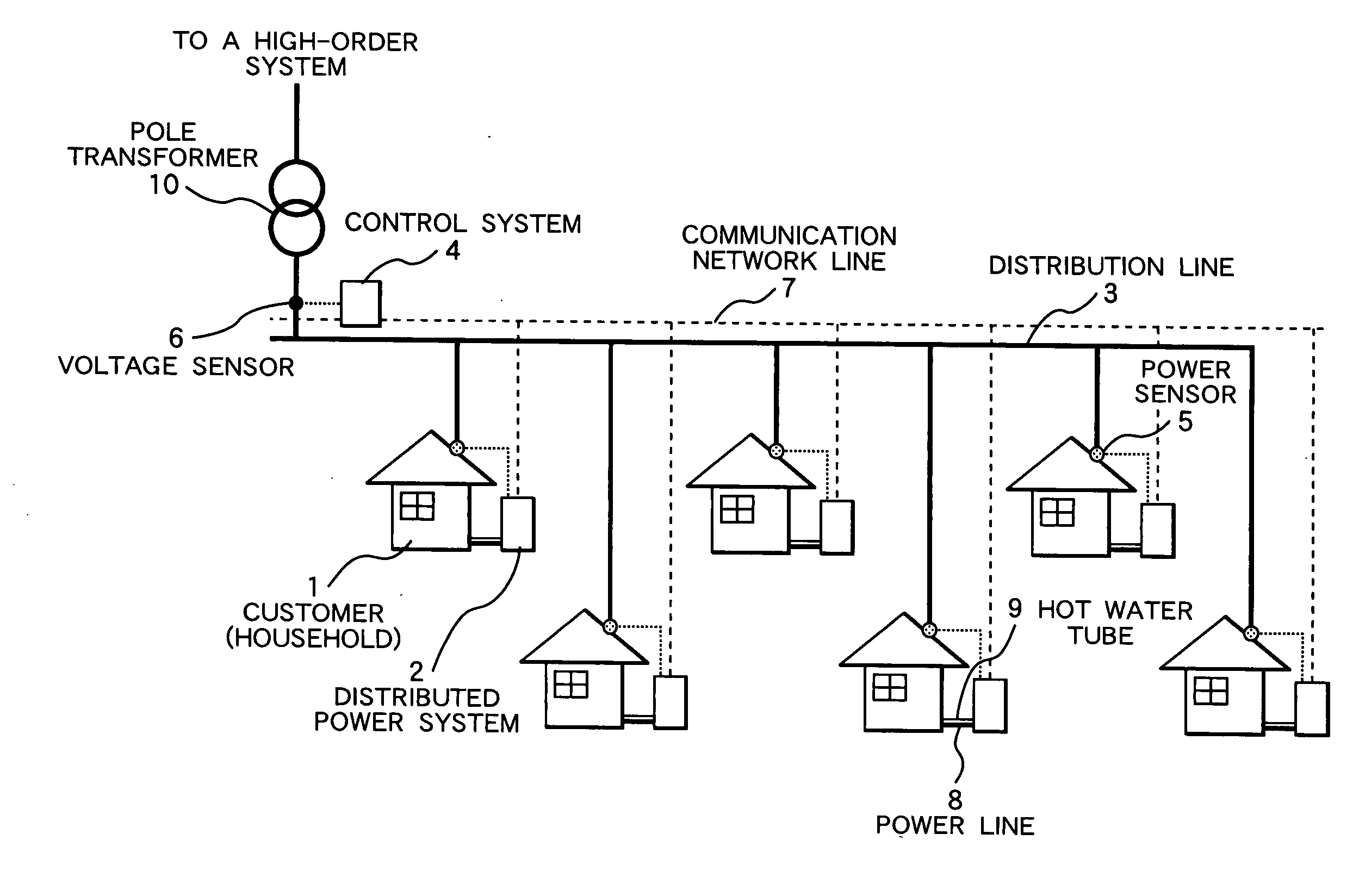
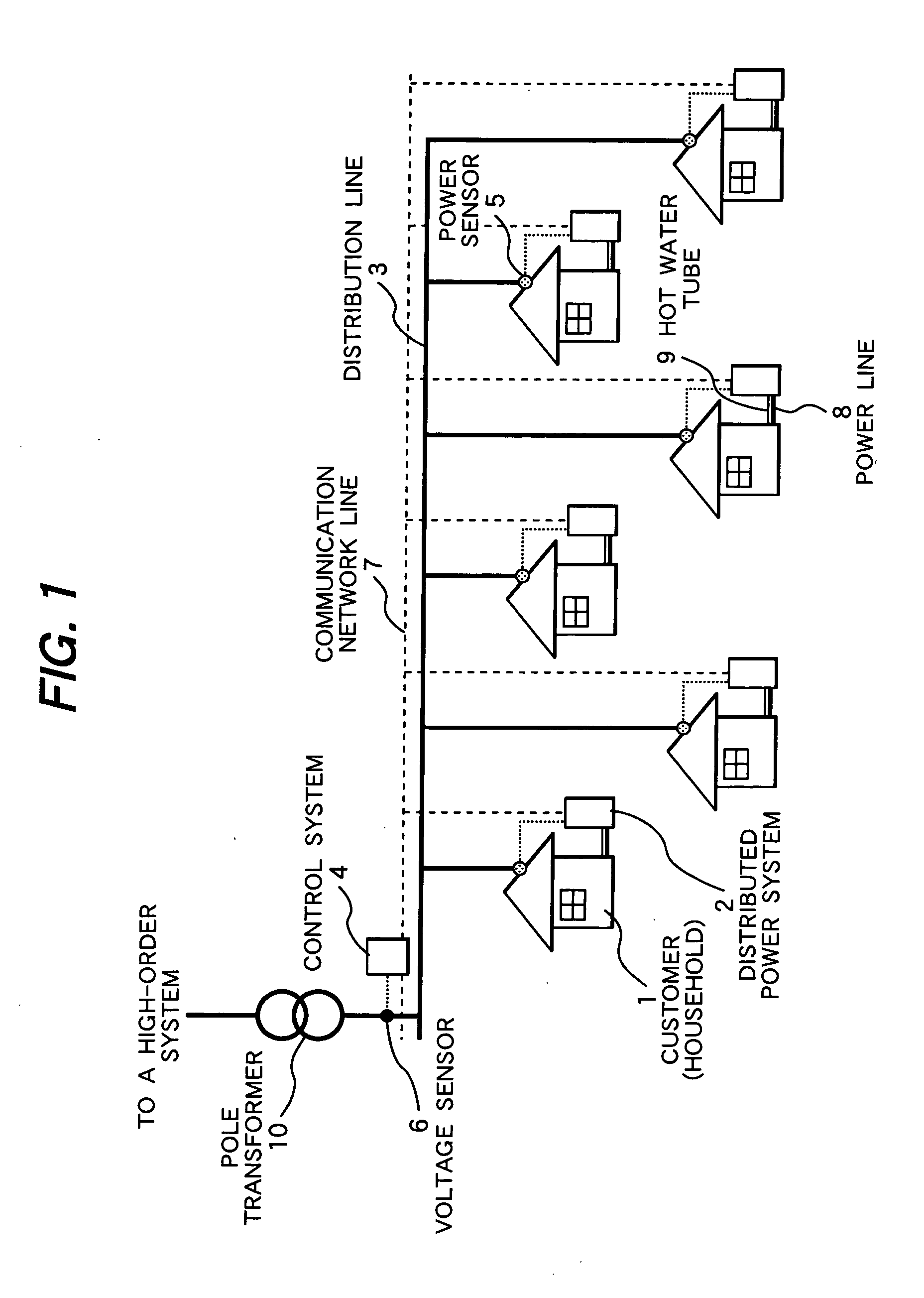
[0038]FIG. 1 is a system configuration diagram representing the first embodiment of the present invention. This system includes a plurality of households 1 as customers, a distributed power generation system 2 installed in each household to generate electric power and heat, a distribution line 3, a control system for controlling the operation of each distributed power generation system, a control system 4 for controlling the operation of each distributed power generation system, a electric power sensor 5 for measuring the electric power flowing into or out of each household, and a voltage sensor 6 for measuring the delivered voltage just at the back of the pole transformer. The distributed power generation system and control system are connected by a communication network line7 to permit exchange of data and control commands. Electric power and hot water generated by the distributed power generation system are supplied to each household through a electric power line 8 and a hot wate...

embodiment 2

[0067]FIG. 6 is a system configuration diagram representing the second embodiment of the present invention. In the example in FIG. 6, the installation positions of the electric power sensor and voltage sensor are different from those in the first embodiment (FIG. 1). In this example, a electric power sensor for measuring the electric energy just at the back of the pole transformer and a voltage sensor for measuring the voltage at the measurement point installed in each household are provided.

[0068]FIG. 7 is a system control flow representing the second embodiment of the present invention. In the second embodiment, the voltage of the distribution system is measured by the voltage sensor installed in each household (S1). Accordingly, the measured voltage value measured by this voltage sensor is transferred to the monitoring section of the control system through the communication network, and is monitored by the monitoring section in real time (S3).

[0069] The system status estimating...

embodiment 3

[0077]FIG. 8 is a system control flow representing the third embodiment of the present invention. The system schematic diagram in this case is the same as that of FIG. 1.

[0078] The procedures up to the steps S7 and S8 in the third embodiment are the same as those in the first embodiment. After that, based on the operation priority of the distributed power generation systems determined by the priority calculation section of the control system, the system status estimating section of the control system performs the step of estimation according to the order wherein the operation priority of the distributed power generation system is higher, to see whether or not the distribution system voltage is kept within the tolerance. This procedure is repeated until the distribution system voltage is kept within the tolerance. Then it detects the combination of the distributed power generation systems wherein the distribution system voltage is kept within the tolerance, and determines the operat...


PUM


Abstract

A control system for cogeneration system provides operation combination calculating means which calculates the combination of operations capable of keeping the voltage of the distribution line within a predetermined tolerance within voltage tolerance based on following (1)-(3). (1) the predicted value of the electric power demand of each customer calculated by electric power demand predicted value calculating means; (2) the impedance of the distribution line recorded by distribution line information recording means; and (3) the combination of cogeneration systems to be operated, as calculated by operation combination calculating means.

Description

CLAIM OF PRIORITY [0001] The present application claims priority from Japanese application serial no. 2005-283231, filed on Sep. 29, 2005, the content of which is hereby incorporated by reference into this application. FIELD OF THE INVENTION [0002] The present invention relates to a control system and a control method for a cogeneration system. BACKGROUND OF THE INVENTION [0003] In recent years, problems of global warming and depletion of natural resources have begun surfacing. There has been a growing concern over the effective use of energy. Particularly in the field of global warming, the Kyoto Protocol providing for a CO2-reduction goal took effect. During the period from 2008 through 2012, Japan is required to reduce the CO2 emission volume by 6% with reference to the 1990 level. Against this background, the distributed power generation provided inside the customer, can be utilized in the form of a cogeneration system that allows the customers to use not only the generated elec...

Claims


Application Information

Patent Timeline
IPC IPC(8): F01B21/04F02G5/04F24D18/00G06Q50/00G06Q50/06H02J3/00H02J3/38H02J3/46H02J13/00
CPCF24D12/02Y02E20/14Y02B30/14F24H2240/00Y02B30/00F24D18/00F24D2101/30F24D2101/10F24D2101/70F24D2101/80
Inventor KOMURA, AKIYOSHIWATANABE, MASAHIRO
Owner HITACHI LTD
Why Eureka
Try Eureka