Multi-layer, light markable media and method and apparatus for using same

a multi-layer, light markable technology, applied in the direction of photosensitive materials, mechanical control devices, identification means, etc., can solve the problems of requiring media sensitive to nir (near, undesirable coloration, cost of narrowband nir absorbers), etc., to reduce the operating speed of the rotary bellows

Inactive Publication Date: 2007-03-29
SINCLAIR SYST INT
View PDF11 Cites 31 Cited by
  • Summary
  • Abstract
  • Description
  • Claims
  • Application Information

AI Technical Summary

Benefits of technology

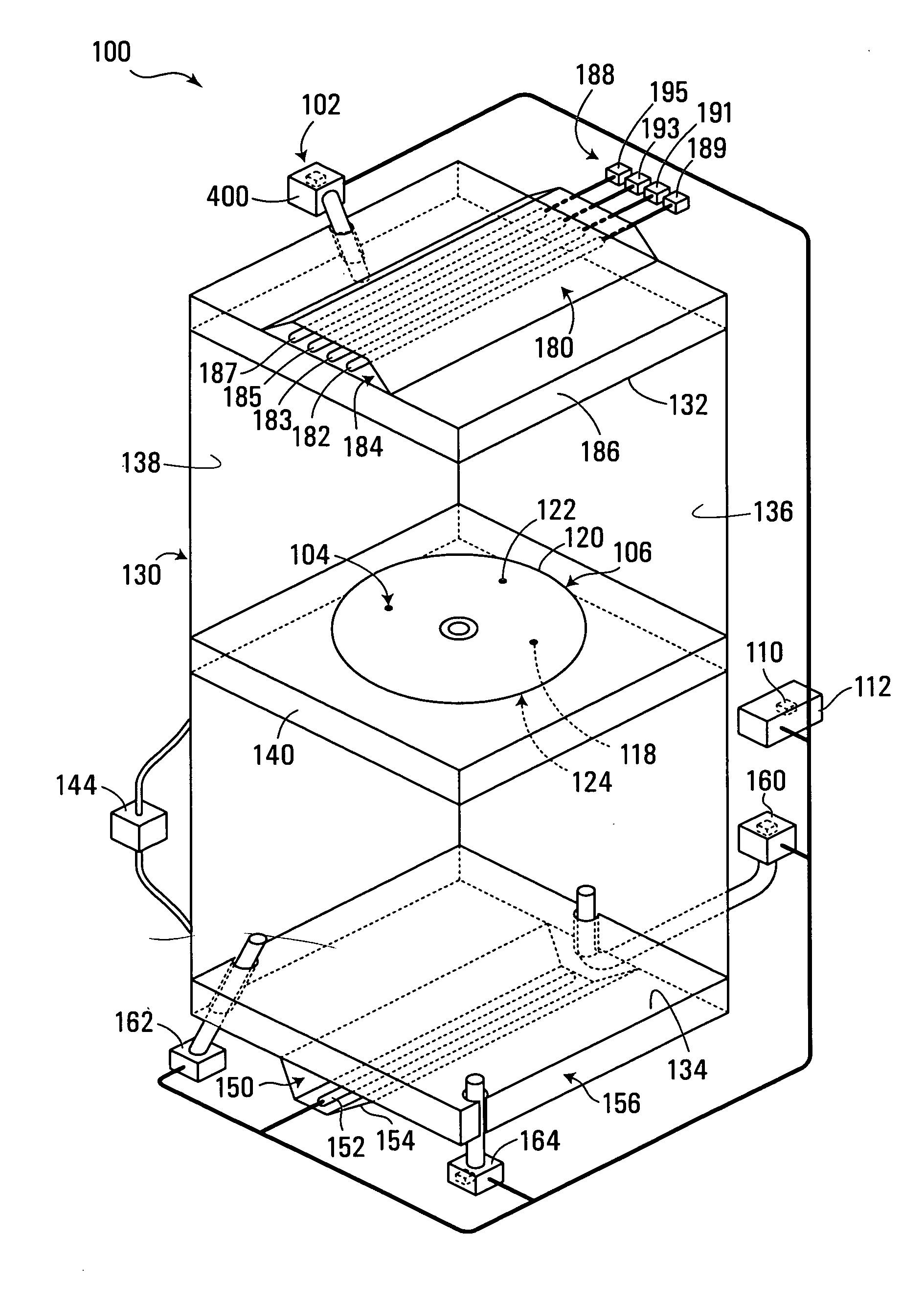
[0019] A further object of the invention is to provide a laminated label design capable of having variable coded information applied to it after the label has been transferred to the tip of a bellows in a rotary bellows applicator, which requires only minor modifications to the rotary bellows label applicating machine.
[0020] A further object of the invention is to provide a laminated label capable of having variable coded information applied to it for use in a rotary bellows applicator without having to reduce the operating speed of the rotary bellows applicator.

Problems solved by technology

A major disadvantage of prior art direct laser marking systems is that they require media sensitive to NIR (near infrared) wavelength of diode lasers.
In most cases, white or clear media is preferred, so coloration is undesirable.
Additionally, narrowband NIR absorbers can be costly, adding significantly to the cost of the media, when used in applications like packaging / product labeling, where costs need to be extremely low.
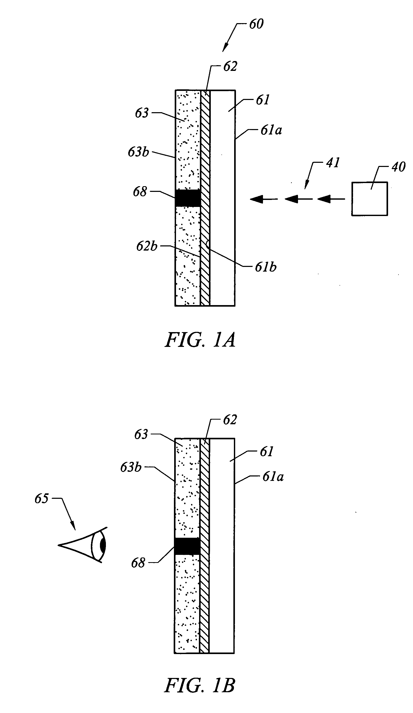
However, that prior art does not teach or suggest the use of carbon black as a light absorbent material wherein the absorbed light is converted to heat and conducted into an adjacent thermochromic layer; neither does it teach or suggest a three layer label laminate having a light absorbent central layer, a thermochromic layer and a substrate.

Method used


Image

  • Multi-layer, light markable media and method and apparatus for using same
  • Multi-layer, light markable media and method and apparatus for using same
  • Multi-layer, light markable media and method and apparatus for using same

Examples


example 2

Set-Up 1

[0139] Laser: 0.20 Watt 980 nm single beam laser

[0140] Coating: Direct Thermal (Typically found on paper labels used in Direct Thermal Printers) with NIR absorber mixed into the direct thermal layer.

[0141] Laminate: Clear LDPE

[0142] Write Speed: 40 cm / s

[0143] Power: Watts

[0144] Label Carrying Material: Black rubber

[0145] Write speed was increased in 5 cm / s increments until the resultant mark was fully marked (i.e. width of the line equal to the full width half maximum laser parameter −80 um). For this setup the write speed was 40 cm / s.

Set-Up 2

[0146] Laser: 0.20 Watt 980 nm single beam laser

[0147] Coating: Direct Thermal (Typically found on paper labels used in Direct Thermal Printers) with NIR absorber mixed into the direct thermal layer.

[0148] Laminate: Clear LDPE

[0149] Write Speed: 40 cm / s

[0150] Power: Watts

[0151] Label Carrying Material: Brushed aluminum

[0152] Again the write speed was increased in 5 cm / s increments until the resultant mark was fully mark...


PUM

PropertyMeasurementUnit
thickaaaaaaaaaa
wavelengthaaaaaaaaaa

Abstract

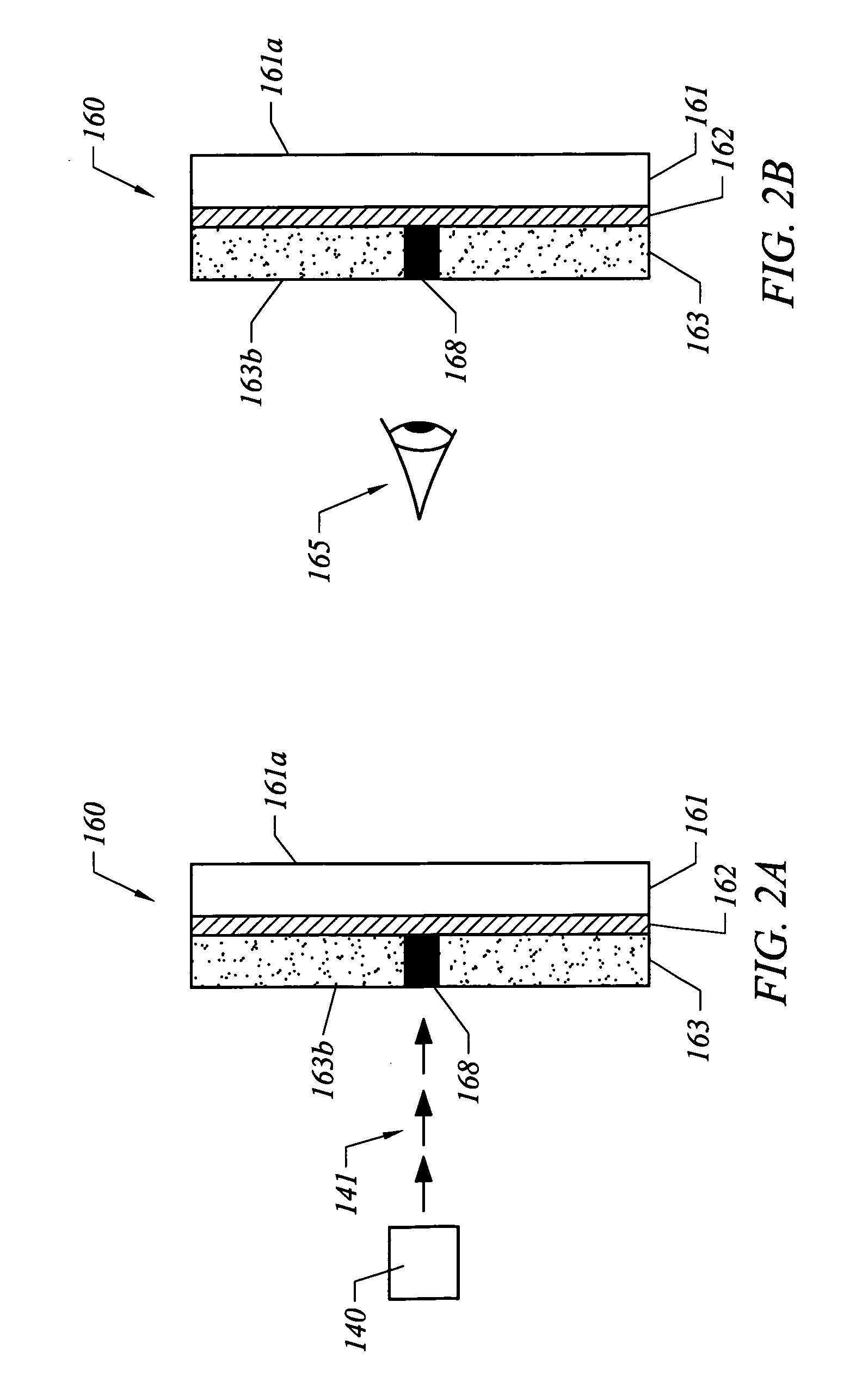
A multi-layer laminate media is provided on which information may be applied in machine or human readable form on a visible front surface by the output of one or more lasers, or other high intensity light source. In a preferred embodiment, the media has three layers including a substrate, a thermochromic layer and a light absorbent layer located intermediate the media substrate and the thermochromic layer. The light absorbent layer is adapted to absorb light from the light source and convert the absorbed light into heat. The heat is immediately conducted into selected portions of the thermochromic layer which is in thermal contact with the light absorbent layer, causing portions of the thermochromic layer to change visual appearance such as color to create the desired mark. The media optimally includes obscuration materials to reduce the visibility of the light absorbent layer to the naked eye. The light absorbent layer is preferably a low cost absorber such as carbon black. An alternate form of the invention is a two layer laminate media including a substrate and a thermochromic layer. The invention is usable in conjunction with labeling produce items. The invention includes a method and apparatus for using media in conjunction with labeling produce items.

Description

CROSS-REFERENCE TO RELATED APPLICATIONS [0001] This application is a continuation-in-part of U.S. application Ser. No. 11 / 069,330 filed Mar. 1, 2005. This application claims the benefit of and priority from U.S. provisional applications Ser. Nos. 60 / 712,640 filed on Aug. 29, 2005 and 60 / 789,505 filed on Apr. 4, 2006.BACKGROUND AND BRIEF SUMMARY OF INVENTION [0002] The present invention relates generally to laser (or other high intensity light) markable media used, for example, as labels in labeling machines and / or in film printing for, packaging, or for other printing applications, including point-of-sale, fax machines and laminate card (e.g. identity card) printers. [0003] The labeling and packaging markets are demanding marking systems that are faster, more cost effective, capable of marking non-flat surfaces that have a longer lifetime, and which are capable of marking labels or packaging films “on the fly.”[0004] As known in the prior art, direct laser array marking of high volu...

Claims


Application Information

Patent Timeline
Patent Type & Authority Applications(United States)
IPC IPC(8): B65C9/46
CPCB41M5/282B41M2205/04Y10T156/1707G09F3/02G11B23/40B65C9/46
Inventor GRIFFIN, NEILHYDE, SAMSCALLY, AYLWYNCLARKE, ROGERHOWARTH, M. SCOTTCALUSDIAN, RICHARDMURRAY, WILSON B.HIRST, RICHARDEVANS, RICHARD
Owner SINCLAIR SYST INT
Why Eureka
Try Eureka