Method and system for LASER machining

a laser machining and laser technology, applied in the field of laser machining methods and systems, can solve the problems of difficult and costly manufacturing of such small features of pore arrays, difficulty in drilling holes with exit diameters less than, and inability to meet the requirements of the application, so as to increase the number of repetitions, reduce the amount of time required, and increase the amount of power.

Inactive Publication Date: 2007-04-05
DAIMAY NORTH AMERICA AUTOMOTIVE +1
View PDF39 Cites 57 Cited by
  • Summary
  • Abstract
  • Description
  • Claims
  • Application Information

AI Technical Summary

Benefits of technology

[0021] A part to be modified by a LASER process or other energy source can be processed more rapidly and precisely by modifying the process in one or more of the following ways: (1) directing the LASER beam at more than a single feature while features are being processed, (2) decreasing the amount of time required to move the beam from feature to feature, (3) increasing the amount of power delivered to the part, preferably by increasing the repetition rate of a pulsed (q-switched) LASER without changing the properties of individual LASER pulses (4) detecting the progress of the process on individual features or subgroups of features, (5) analyzing the progress detected, and (6) modifying or terminating the process on individual features or subgroups of features in response to the information obtained by monitoring the progress of the process.

Problems solved by technology

Pore arrays having such small features can be difficult and costly to manufacture.
There are several disadvantages to this approach.
In addition, the non-uniform output beam generally seen with excimer LASERs usually requires the use of homogenizers, and even then this technology has uniformity limitations.
It is difficult to drill holes with exit diameters less than 1 micrometer using the process as described in U.S. Pat. No. 4,508,749.
It is difficult to achieve good beam homogeneity across excimer LASER beams, and beam power variations can also be introduced when multiplexing other types of LASERs.
Thus, this control method faces limitations in feature-to-feature (hole-to-hole) uniformity within multiple feature arrays machined in a single operation.
Although the feedback control method of U.S. Pat. No. 6,624,885 can be applied to a process that drills only one hole at a time, this seriously limits the production speed of such a process due to the requirement to step the target or beam from hole to hole, and then allow for settling time.
This could result in speeding the process up by more than 100 times. However, it also reduces the time between pulses from more than 1 millisecond to only 10 microseconds.
However, as this discussion indicated, spatially multiplexing the beam can result in non-uniformity between the individual features within the multiplicity, and it can be difficult to control the characteristics of the individual features.
However, for the nozzles used in aerosol drug delivery, this may require independently controlling hundreds of LASER beams based on the feedback from a detector with hundreds or thousands of elements.
In addition, machining a large array at once may in itself lead to plasma shielding effects.

Method used


Image

  • Method and system for LASER machining
  • Method and system for LASER machining
  • Method and system for LASER machining

Examples


example 1

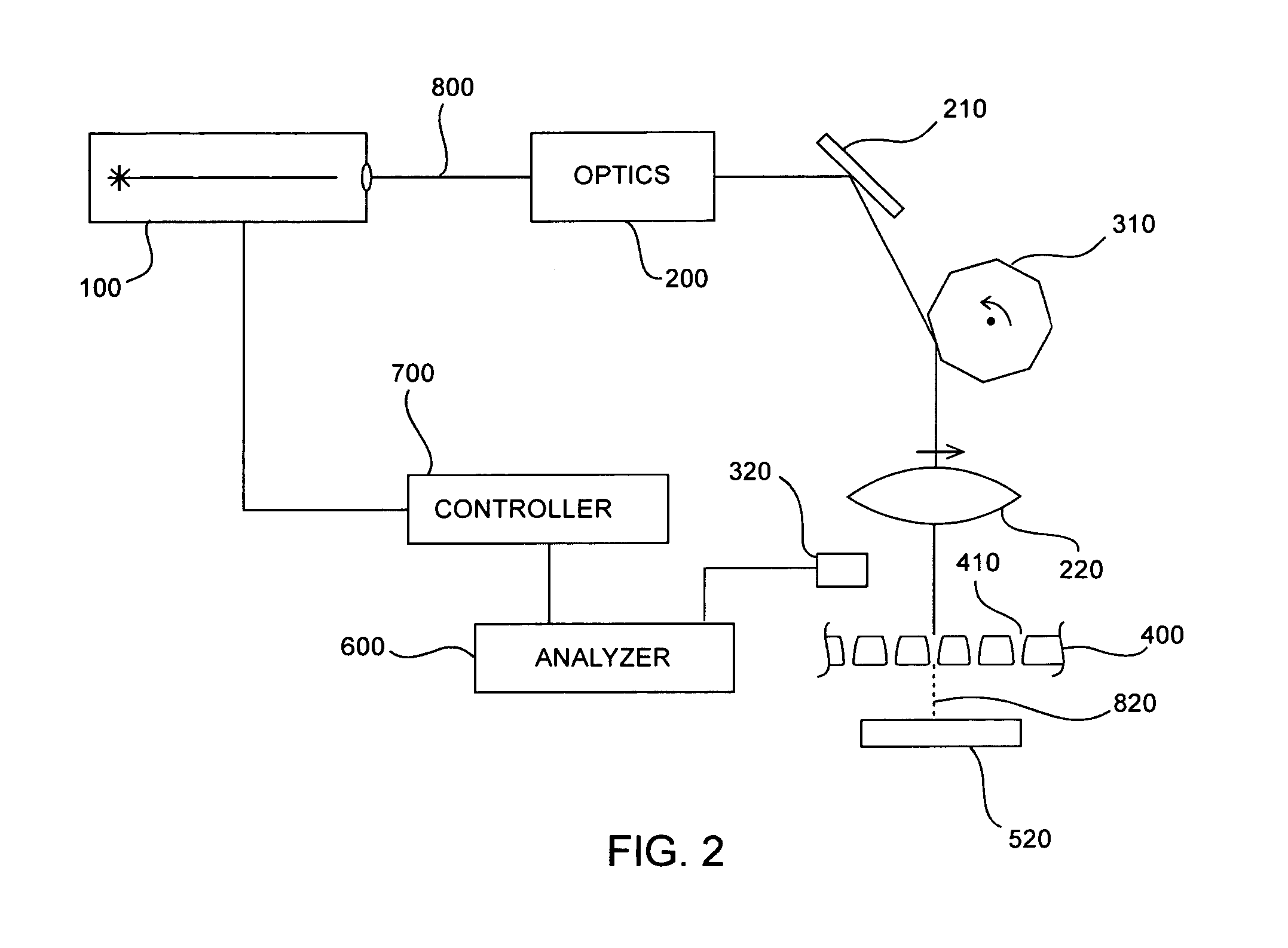
[0093] In this example, a single-hole LASER drilling process was developed based a 5 kHz LASER pulse rate, and a higher processing speed was desired. Later, a LASER with a 100 kHz pulse rate became available. Rather than increasing the pulse rate on a single feature, the beam can be scanned repeatedly across the work piece at 5 kHz or less using an oscillating mirror (340, FIGS. 4 and 5). The LASER pulses are synchronized with the oscillation of the mirror using a detector (320) with a narrow slit covering the sensitive surface, placed next to the part to be machined. As the beam scans across the slit, the LASER (100) is triggered to pulse in high-energy mode, so that high energy pulses are repeatedly directed to the same set of sequential locations (410). In this way, each of 20 or more different locations are each exposed to 5 kHz or less drilling operations using a single 100 kHz LASER. In the previously developed process, the drilling on a single hole is terminated when a certai...

example 2

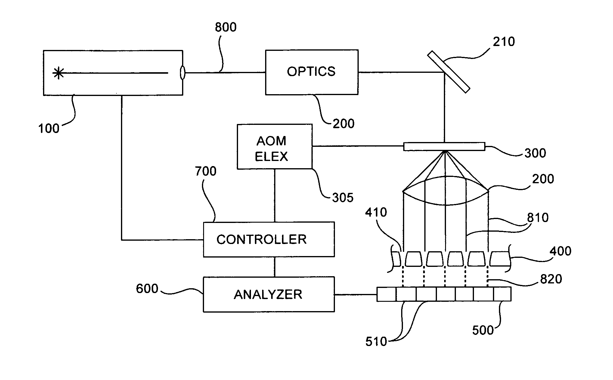
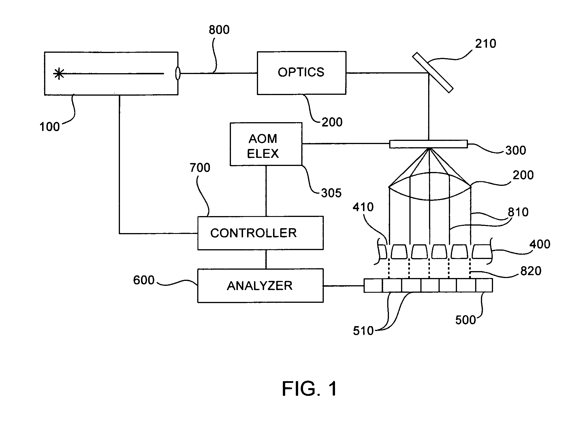
[0094] In this example, a single-hole LASER drilling process was developed based on a 5 kHz pulse repetition rate, and a higher processing speed was desired. In order to drill many holes at once, the LASER beam can be split into many beams using an acousto-optic modulator. This splitting can be in one or two dimensions, but one dimensional splitting is simpler and easier to explain and is used in this example (FIG. 1). Each beam (810) is formed by the incident LASER beam (800) interacting with a density variation in the acousto-optic element (300). The density variation results from a sound wave typically generated by driving the acousto-optic element with an electrical signal of an appropriate frequency. Thus each beam corresponds to a frequency and the beam intensity can be adjusted by adjusting the amplitude of the electrical signal at that frequency. All of the signals are combined electrically and applied to the acousto-optic element to generate all of the beams at once. In the...

example 3

[0095] In this example, 10 holes are drilled at once using a laser pulsing at 100 kHz and directing each pulse sequentially at the 10 holes consecutively. The system described above can be used, but with the synthesizer driving the AOD reprogrammed to multiplex the pulses to the 10 holes in time, —using the same pre-programmed sequence for each one. The synthesizer then synchronizes with the laser pulsing and the detector response, tracking which of the 10 holes has been processed to completion and skipping those holes. In either case, the synthesizer returns control to the next level controller in the system once it has completed drilling the 10 holes.


PUM

PropertyMeasurementUnit
diametersaaaaaaaaaa
diameteraaaaaaaaaa
diameteraaaaaaaaaa

Abstract

The invention provides a method of rapidly machining multiple, often similar or nearly identical, features using a LASER machining system. During LASER machining, light of a wavelength and intensity that will modify the workpiece to be machined is directed at the workpiece and interacts to produce the desired change. If several features are to be machined, the processing speed can be increased by operating on a multiplicity of features at once. In one embodiment of the invention, this is achieved by separating the LASER beam into multiple beams and machining the desired features simultaneously.

Description

CROSS-REFERENCE [0001] This application claims the benefit of U.S. Provisional Application No. 60 / 723,382, filed Oct. 3, 2005, which application is incorporated herein by reference noting that the current disclosure governs with respect to any differences with the provisional application.FIELD OF THE INVENTION [0002] The present invention relates to methods of and systems for LASER machining. More specifically, it relates to increasing processing speed and quality by multiplexing a LASER machining beam in either space or time while measuring a response and modifying the operating parameters of the multiplexed beams. BACKGROUND OF THE INVENTION [0003] In different areas of technology it is desirable to make use of a thin sheet of material which has an array of regularly spaced, very small holes therein. For example, such might be used in the manufacture of various electronic components. Thin sheets which have one or more holes in them could also be used in the formation of components...

Claims


Application Information

Patent Timeline
Patent Type & Authority Applications(United States)
IPC IPC(8): B23K26/00
CPCB23K26/03B23K26/032B23K26/034B23K26/04B23K26/0626B23K26/0643B23K26/067B23K26/0673B23K26/0676B23K26/0807B23K26/0815B23K26/0853B23K26/381B23K26/388B23K26/4065B23K2201/16B23K2203/00B23K26/043B23K26/4005B23K26/4075B23K26/408B23K26/0821B23K26/082B23K26/382B23K26/40B23K26/389B23K2101/16B23K2103/42B23K2103/50B23K2103/52
Inventor WILBANKS, THOR MILLERSCHUSTER, JEFFREY A.
Owner DAIMAY NORTH AMERICA AUTOMOTIVE
Why Eureka
Try Eureka