Ink jet recording apparatus, nozzle inspection method and program thereof

a recording apparatus and nozzle technology, applied in the direction of printing, other printing apparatus, etc., can solve the problem of not easy to accumulate at the print head

Inactive Publication Date: 2007-04-05
SEIKO EPSON CORP
View PDF2 Cites 8 Cited by
  • Summary
  • Abstract
  • Description
  • Claims
  • Application Information

AI Technical Summary

Benefits of technology

[0006] The present invention has been made to solve such the problem and aims to provide an ink jet recording appara

Problems solved by technology

In this context, while the print recording liquid tends to accumulate easily in the print re

Method used


Image

  • Ink jet recording apparatus, nozzle inspection method and program thereof
  • Ink jet recording apparatus, nozzle inspection method and program thereof
  • Ink jet recording apparatus, nozzle inspection method and program thereof

Examples


Embodiment Construction

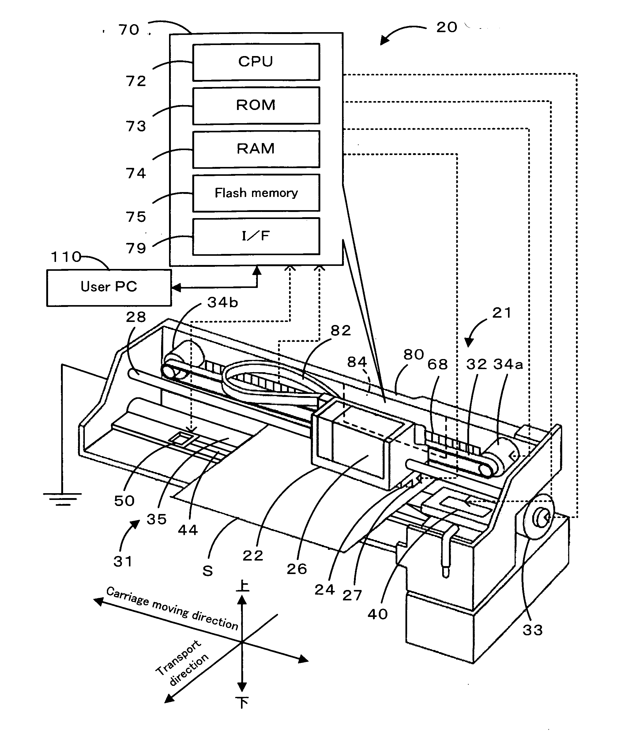
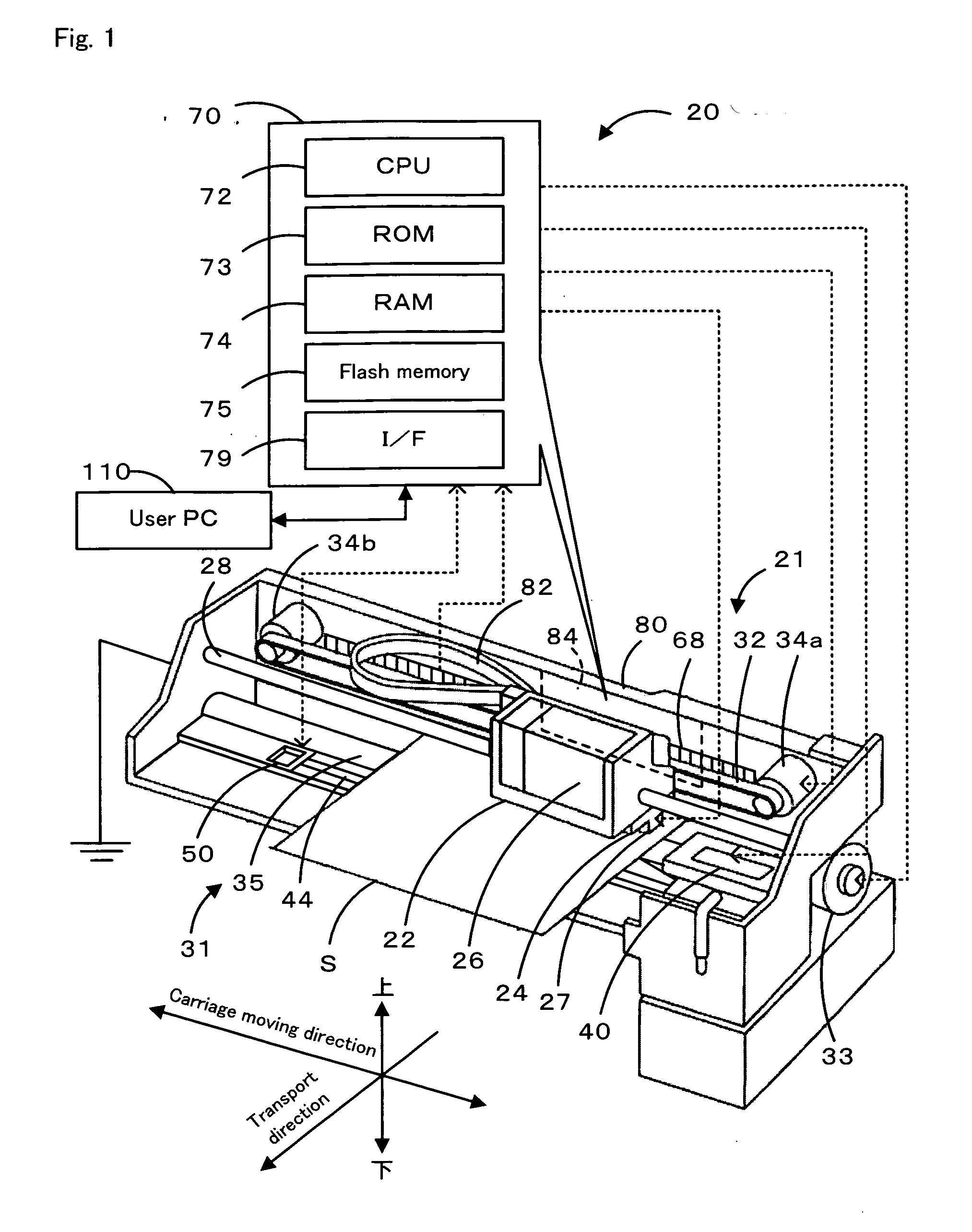
[0034] Next, one embodiment of the present invention will be described. FIG. 1 is a block diagram schematically illustrating a configuration of an ink jet printer 20 that is this embodiment. FIG. 2 is a perspective view when a carriage 22 is viewed from the lower side of a rear face. FIG. 3 is a left side elevation of the carriage 22 (this is a broken-out section view, and a partially enlarged illustration is shown inside the circle). FIG. 4 is an illustration of an electrical wiring connection of a print head 24. FIG. 5 is an illustration of a paper handling mechanism 31. FIG. 6 is a block diagram schematically illustrating a configuration of a nozzle inspection device 50.

[0035] As shown in FIG. 1, the ink jet printer 20 of this embodiment comprises a printer mechanism 21 that performs printing by ejecting ink droplets onto a recording sheet S that is carried over a platen 44 from the back to the front, a paper handling mechanism 31 that includes a line feed roller 35 driven by a ...


PUM


Abstract

In this ink jet printer, on the basis of voltage of a nozzle plate 27 at the time that a print head 24 is driven and in a state in which a predetermined potential difference has been generated between the nozzle plate 27 and the inspection area 52, a nozzle inspection is performed so as to confirm whether or not ink is in practice being ejected from each nozzle 23, so that ink can be sequentially ejected to an inspection area 52 from each nozzle. According to the nozzle inspection voltage change is detected in the nozzle plate 27 by a voltage detection circuit 54 provided on an encoder board 64 on a carriage 22. Since both the nozzle plate 27 and the voltage detection circuit 54 are installed on the carriage 22, and the distance between the two of them is shorter, they are less likely be affected by noise. In addition, there is no need to prepare a new board on which the voltage detection circuit 54 needs to be mounted.

Description

BACKGROUND OF THE INVENTION [0001] 1. Field of the Invention [0002] The present invention relates to an ink jet recording apparatus, a nozzle inspection method and a program thereof. [0003] 2. Description of the Related Art [0004] Conventionally, as discussed in Patent Document 1, for instance, an ink jet recording apparatus is known that, by not only grounding to the ground a capping member for capping a nozzle area of a print head at the time that printing has been stopped, but also by applying voltage to the print head, generates a potential difference between the print head and an inspection area provided within the capping member, causes an electric field detection unit provided on the capping member to detect any change in field intensity between the print head and the inspection area when ink droplets charged on the print head in that condition fly out, thereby confirming whether or not any ink droplets have actually flown out. As this type of inspection is believed to employ...

Claims


Application Information

Patent Timeline
IPC IPC(8): B41J29/38
CPCB41J2/16579B41J29/393
Inventor KOMATSU, SHINYA
Owner SEIKO EPSON CORP
Why Eureka
Try Eureka