Circulating fluidized bed reactor with a convertible combustion method

a technology of fluidized bed reactor and combustion method, which is applied in the direction of combustion type, furnace, steam separation arrangement, etc., can solve the problems of reducing the efficiency of fossil fuel power plants where such technology is used, consuming considerable energy, and reducing the efficiency of such fossil fuel power plants by more than fifteen percentage points

Inactive Publication Date: 2007-04-12
GENERAL ELECTRIC TECH GMBH
View PDF9 Cites 24 Cited by
  • Summary
  • Abstract
  • Description
  • Claims
  • Application Information

AI Technical Summary

Benefits of technology

[0010] It is an object of the present invention to provide a circulating fluidized bed reactor, which has been designed specifically to operate with air being employed for combustion purposes and, with a minimum...

Problems solved by technology

Such technology for its implementation consumes considerable energy and substantially decreases the efficiency of the fossil fuel power plants where such technology is utilizes, that is, decreases the efficiency of such fossil fuel power plants by more than fifteen percentage points.
However, according to this p...

Method used


Image

  • Circulating fluidized bed reactor with a convertible combustion method
  • Circulating fluidized bed reactor with a convertible combustion method
  • Circulating fluidized bed reactor with a convertible combustion method

Examples


first embodiment

[0048] According to the circulating fluidized bed reactor of the present invention as described herein and as illustrated in FIGS. 1 to 8 of the Drawings, the circulating fluidized bed reactor is of the type similar to that which is described and illustrated in patent document WO 03 / 038338 that has been filed by the same Assignee as the present patent application.

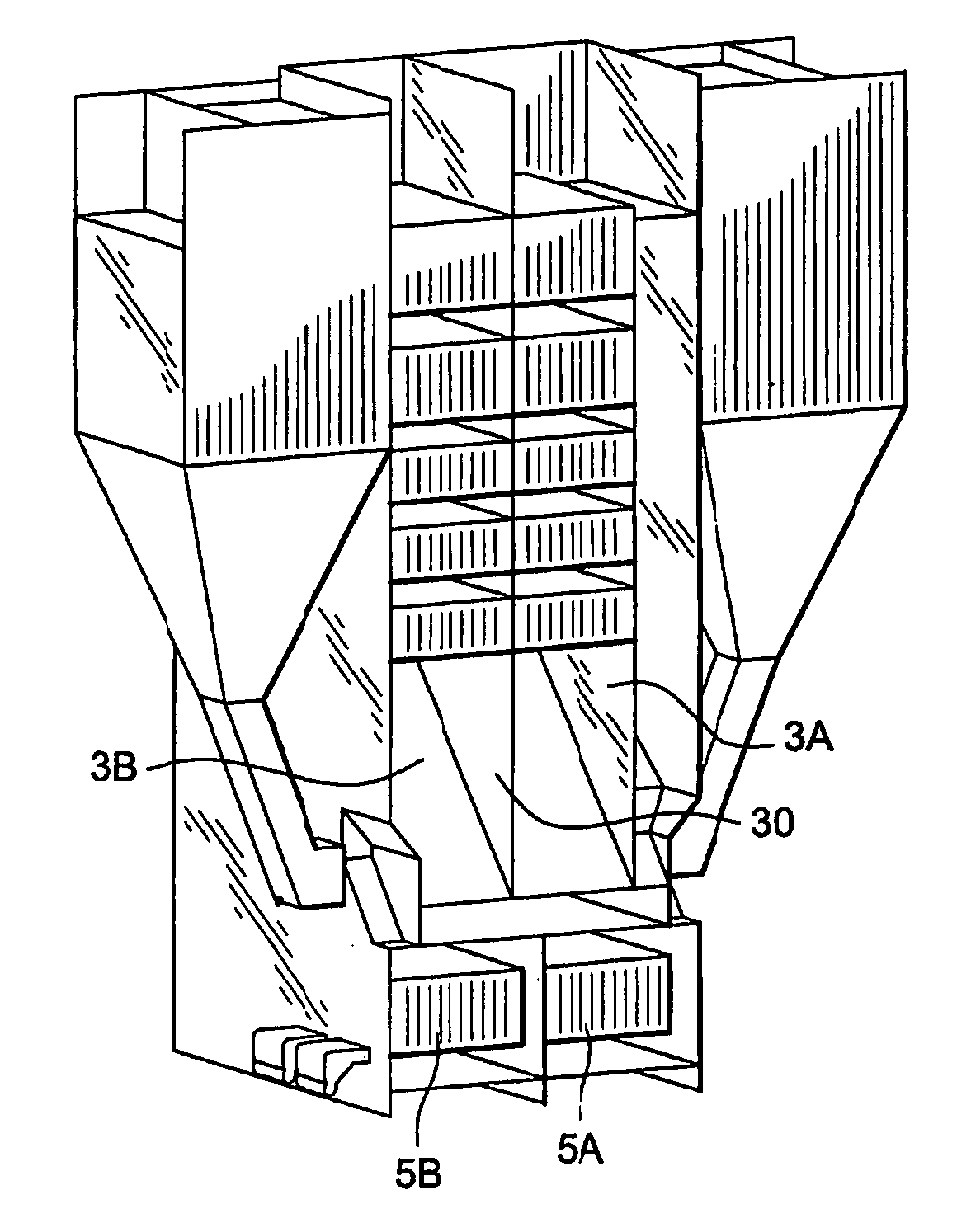
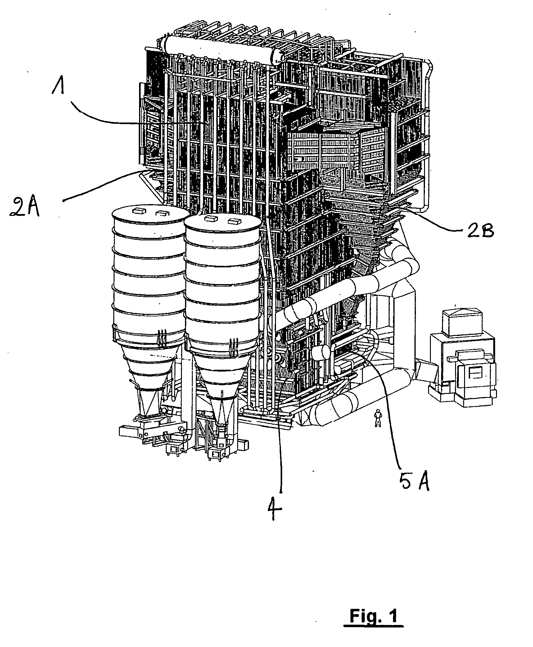
[0049] To this end, this circulating fluidized bed reactor comprises a reaction chamber 1 horizontally bounded by vertical walls, two centrifugal separators 2A and 2B and a heat recovery element referred to herein as a heat exchanger cage 3, which is located behind the reaction chamber 1. This circulating fluidized bed reactor further comprises means for introducing a fluidization gas into the reaction chamber 1 for purposes of maintaining a circulating fluidized bed of particles in this reaction chamber 1. A wind box 4 located under the reaction chamber 1 is utilized for this purpose. This circulating fluidized bed reactor...

second embodiment

[0084] In the second embodiment as described hereinafter and as illustrated in FIGS. 9 to 12 of the Drawings, the circulating fluidized bed reactor is of a similar type as that described in patent document WO 2004 / 036118 filed by the same Assignee as the present patent application.

[0085] According to this prior document wherein a modular system is employed, a circulating fluidized bed reactor may comprise a reaction chamber horizontally bounded by vertical walls, n centrifugal separators that are provided with flue gas outlet ducts connecting each pair of such separators to a rear heat exchanger cage and an exchanger cage located behind the reaction chamber 1, and with the reaction chamber 1 having each of it's the reaction chamber's vertical or side walls positioned so as to be common with a vertical or side wall of a set of n / 2 separators.

[0086] The embodiment, which is specifically described in accordance with the preferred version thereof, is the embodiment wherein for such sep...


PUM


Abstract

The invention relates to a circulating fluidized bed reactor designed to be fed with air and convertible to operate with an oxygen-rich mixture, comprising a reaction chamber (1) horizontally bounded by vertical walls, at least two centrifugal separators (2A, 2B) and a heat recovery element called a heat exchanger cage (3), a reactor also comprising means for introducing a fluidization gas into the reaction chamber using at least one wind box (4) placed under the reaction chamber, and for maintaining a circulating fluidized bed of particles in said chamber, means for transferring gas which must be dedusted from the chamber to the separators, means for discharging the particles separated from the separators and means for transferring the dust-free gases from the separators to the exchanger cage. According to the invention:
    • said reaction chamber comprises at least one partially internal vertical partition wall (10) forming two subchambers (1A, 1B) communicating together and each communicating with at least one separator,
    • said exchanger cage (3) comprises a partially internal vertical partition wall (30) forming two subcages (3A, 3B) communicating together and each communicating with at least one separator, these partition walls being arranged in order to create a passage for the flow of the flue gases into one of said subchambers and into one of said subcages corresponding to operation by oxygen feed in the reaction chamber.

Description

BACKGROUND OF THE INVENTION [0001] The present invention relates to a circulating fluidized bed reactor and a convertible combustion method applicable thereto. [0002] The development of new regulations limiting greenhouse gas emissions, including carbon dioxide in fossil fuel power plants, is leading to the implementation of technologies for capturing the carbon dioxide present in the flue gases that are produced as a result of the combustion of fuel in the presence of air. [0003] The technology frequently used to capture carbon dioxide consists of scrubbing the flue gases that have been diluted with nitrogen from the air employed for combustion purposes using solvents, which absorb the carbon dioxide and then restore the carbon dioxide as a concentrated carbon dioxide gas stream after the solvent has been regenerated by the heating thereof. [0004] Such technology for its implementation consumes considerable energy and substantially decreases the efficiency of the fossil fuel power ...

Claims


Application Information

Patent Timeline
IPC IPC(8): F22B37/26
CPCF23C10/10F23L7/007F23L2900/07001Y02E20/322Y02E20/344Y02E20/32Y02E20/34
Inventor MORIN, JEAN-XAVIERBEAL, CORINNESURANITI, SILVESTREFLORES, EMMANUELBAGLIONE, DANIEL
Owner GENERAL ELECTRIC TECH GMBH
Why Eureka
Try Eureka