
Nitride semiconductor substrate, and method for working nitride semiconductor substrate

Inactive Publication Date: 2007-04-12
SUMITOMO ELECTRIC IND LTD
View PDF5 Cites 2 Cited by
  • Summary
  • Abstract
  • Description
  • Claims
  • Application Information

AI Technical Summary

Benefits of technology

[0007] The present invention was conceived in light of this situation, and it is an object thereof to provide a nitride semiconductor substrate and a method for working a nitride semiconductor substrate, with which the position of a mark indicating crystal orientation can be determined very accurately.

Problems solved by technology

However, an orientation flat on a gallium nitride substrate is not always positioned accurately enough, and there is a need for greater positional accuracy.

Method used


Image

  • Nitride semiconductor substrate, and method for working nitride semiconductor substrate
  • Nitride semiconductor substrate, and method for working nitride semiconductor substrate
  • Nitride semiconductor substrate, and method for working nitride semiconductor substrate

Examples


Embodiment Construction

[0023] Embodiments of the present invention will now be described in detail through reference to the appended drawings. In the description of the drawings, those elements that are the same or equivalent are numbered the same, and will not be described more than once.

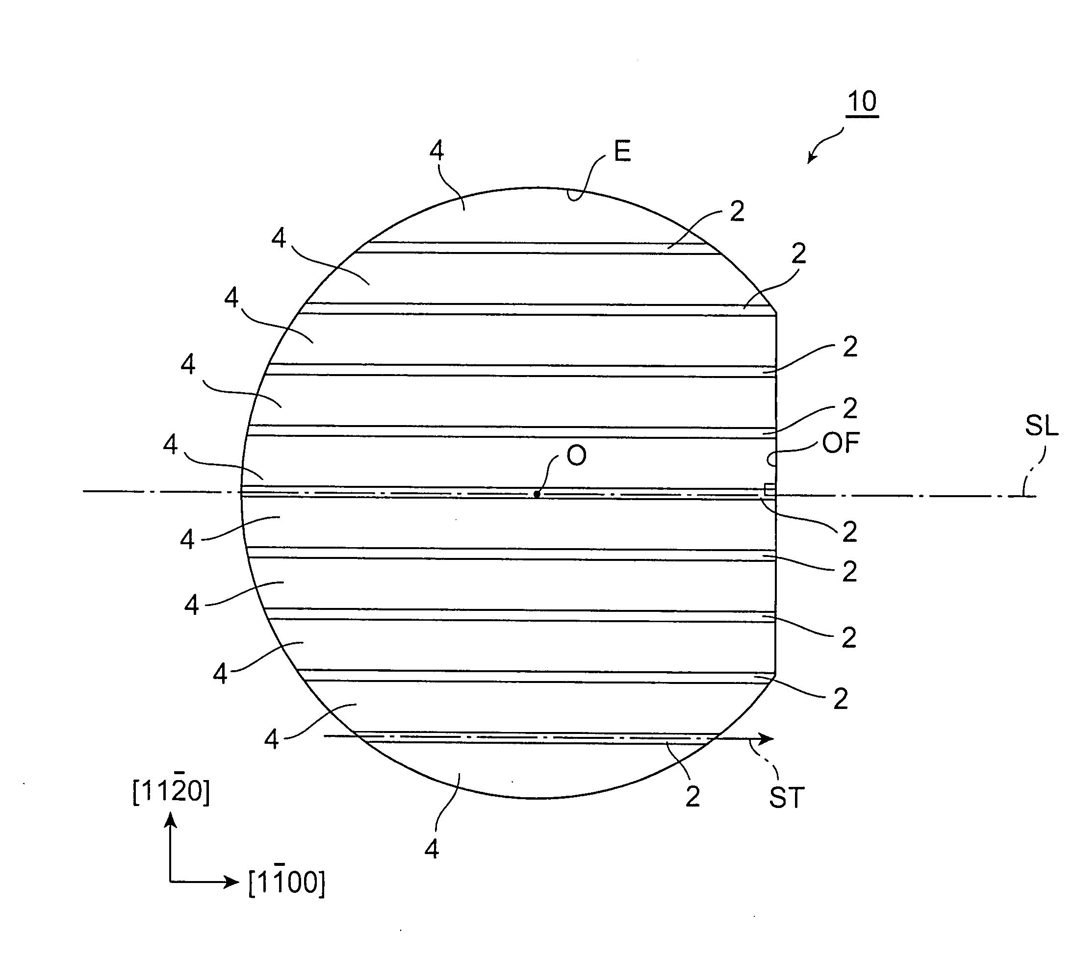
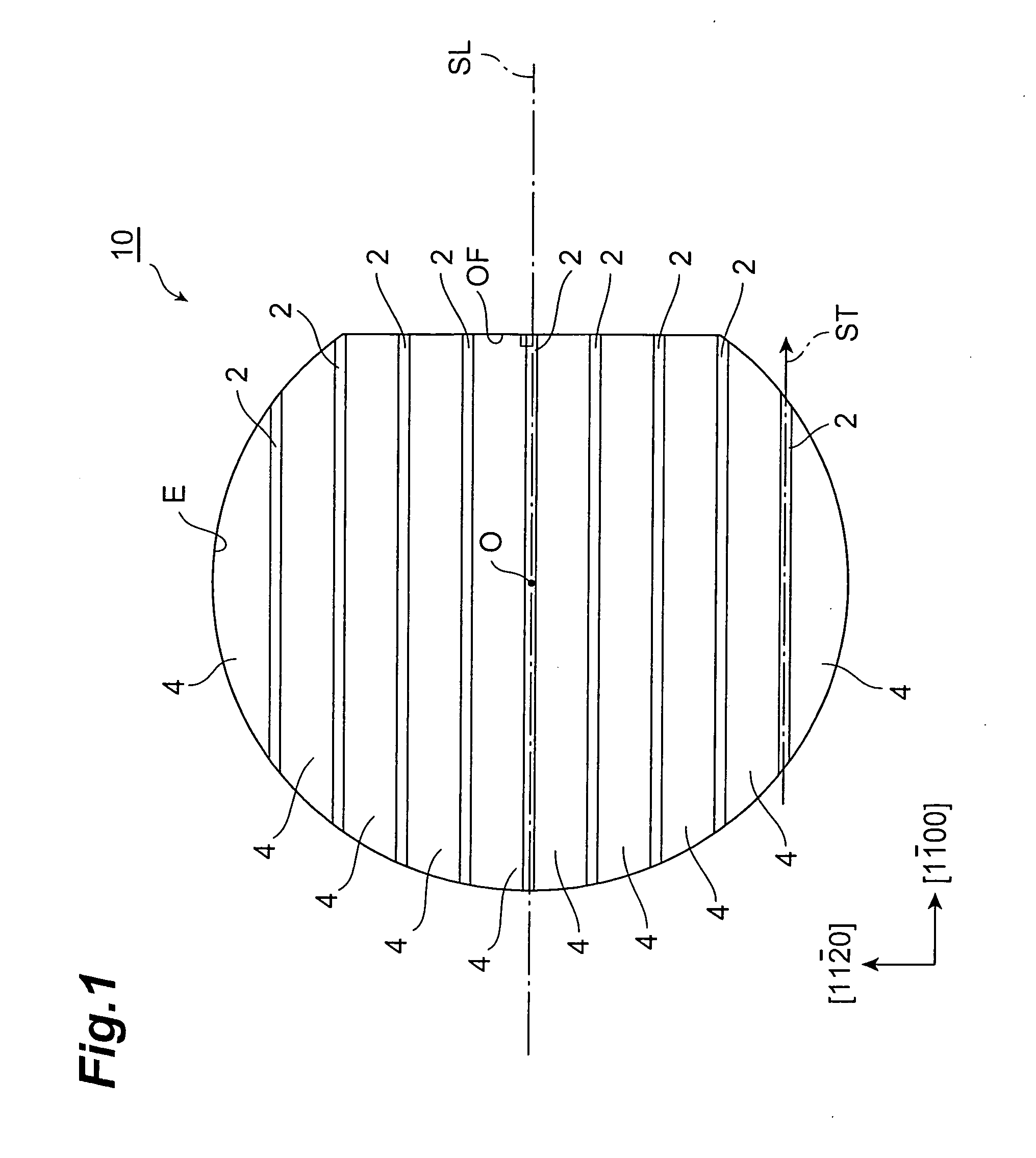
[0024]FIG. 1 is a plan view schematically illustrating the nitride semiconductor substrate in an embodiment. The nitride semiconductor substrate 10 shown in FIG. 1 has an arc-shaped edge E. The nitride semiconductor substrate 10 is a gallium nitride wafer, for example. The nitride semiconductor substrate 10 can be used favorably in a semiconductor laser, LED, or other such semiconductor optical device, for example.

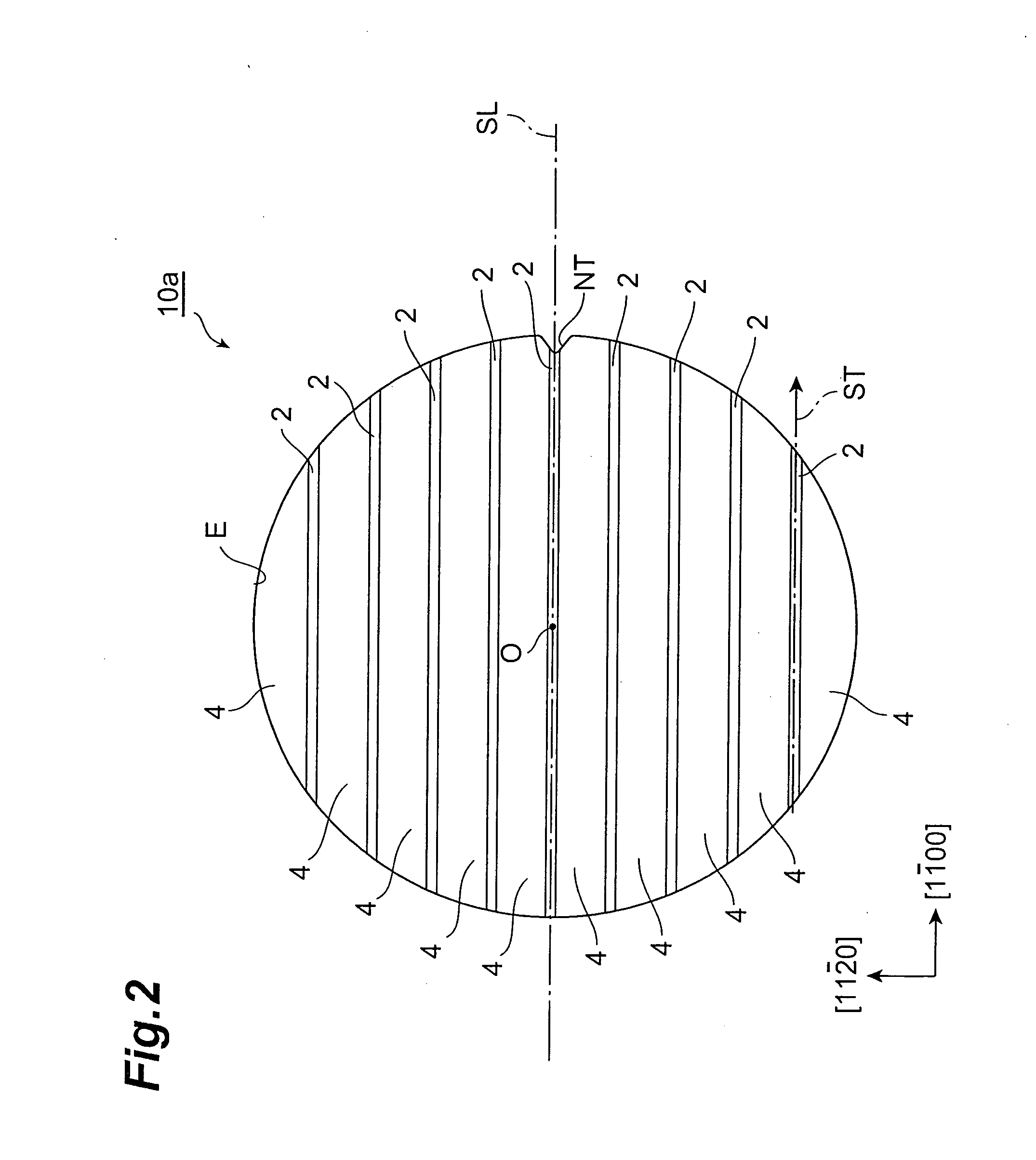
[0025] The nitride semiconductor substrate 10 comprises a plurality of striped regions 2, and a plurality of single crystal regions 4 that are separated by the striped regions 2. The striped regions 2 are comprised of defect concentration regions in which the crystal defect density (dislocation density) is hi...


PUM


Abstract

A method for working a nitride semiconductor substrate, comprising the steps of: preparing a disk-shaped nitride semiconductor substrate comprising a plurality of striped regions having defect concentration regions in which crystal defect density is higher than in surrounding low defect regions; and forming a cut-out at a specific location along the edge of the nitride semiconductor substrate, using as a reference the direction in which at least one from among the plurality of striped regions extends.

Description

BACKGROUND OF THE INVENTION [0001] 1. Field of the Invention [0002] The present invention relates to a nitride semiconductor substrate and to a method for working a nitride semiconductor substrate. [0003] 2. Related Background Art [0004] Various kinds of gallium nitride substrate (GaN substrate) have been known in the past (see Japanese Laid-Open Patent Applications 2003-183100, 2004-335645, and 2000-12900). Japanese Laid-Open Patent Application 2004-335645 discusses a gallium nitride wafer having an orientation flat (OF) as a mark indicating crystal orientation. This orientation flat is formed by first confirming the crystal orientation by X-ray diffraction, and then grinding the wafer. [0005] Japanese Laid-Open Patent Application H7-307316 discusses a method for forming an orientation flat on a wafer composed of a semiconductor compound other than GaN, such as GaAs, GaP, or InP. Japanese Laid-Open Patent Application H2-291146 discusses a method for detecting the position of an ori...

Claims


Application Information

Patent Timeline
IPC IPC(8): H01L33/00H01L29/24H01L21/00H01L21/02H01L21/304
CPCC30B29/40C30B29/406C30B33/00H01L23/544H01L29/045H01L29/2003H01L29/32H01L33/0095H01L2223/54453H01L2223/54493H01L2924/0002H01L2924/00
Inventor NISHIURA, TAKAYUKIMEZAKI, YOSHIO
Owner SUMITOMO ELECTRIC IND LTD
Learn More