Piezoelectric device and method for manufacturing the piezoelectric device

US20070080758A1Inactive Publication Date: 2007-04-12SEIKO EPSON CORP

Image

  • Piezoelectric device and method for manufacturing the piezoelectric device
  • Piezoelectric device and method for manufacturing the piezoelectric device
  • Piezoelectric device and method for manufacturing the piezoelectric device

Examples


Embodiment Construction

[0046] Embodiments of the invention will now be described with reference to the drawings.

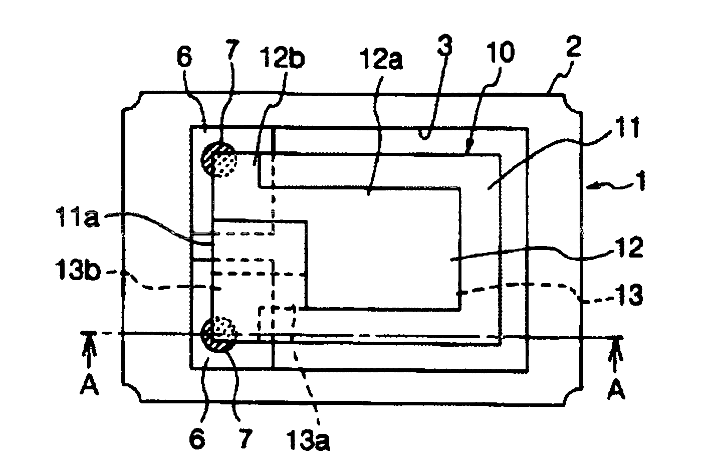
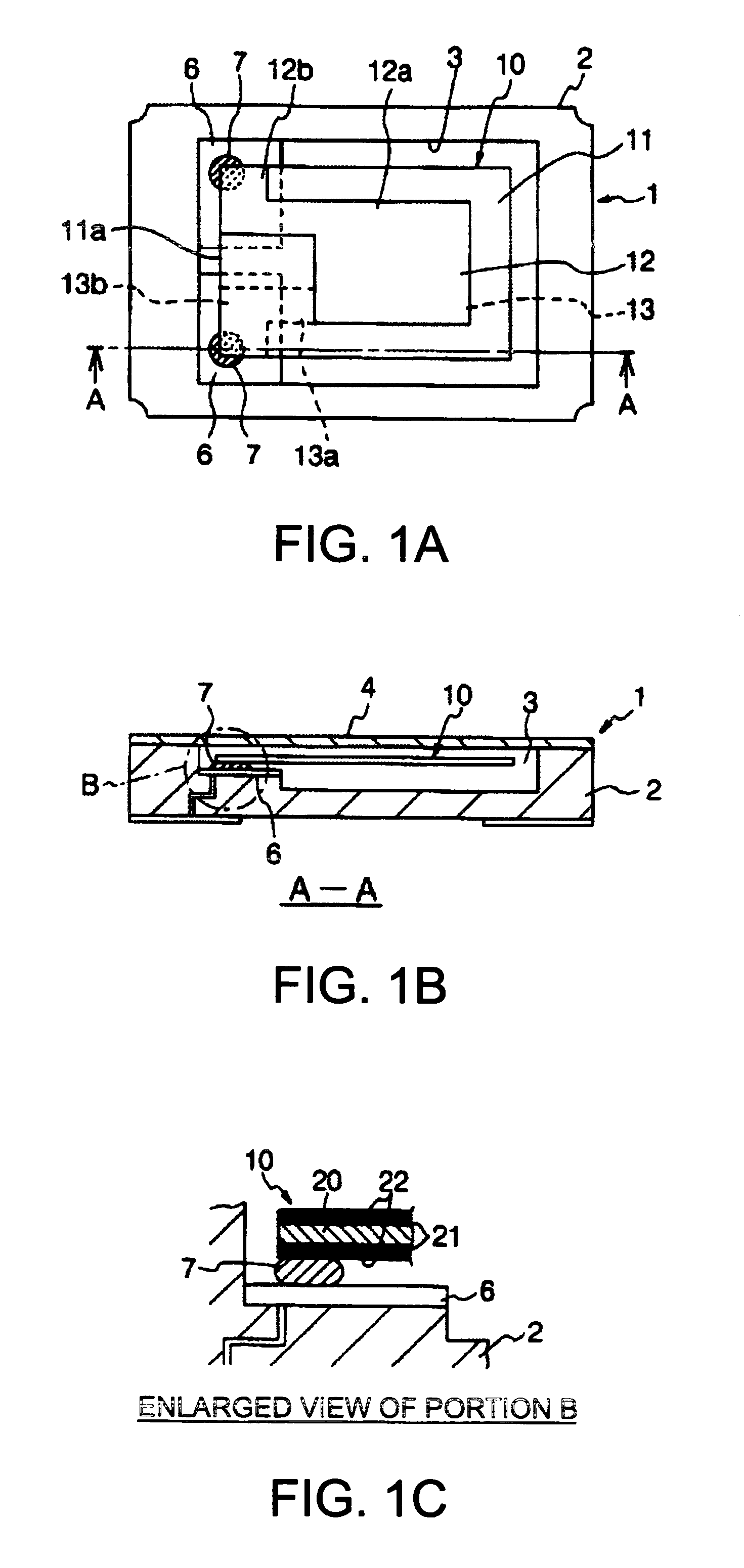
[0047]FIGS. 1A, 1B, and 1C illustrate a structure of a piezoelectric resonator according to one embodiment of the invention. Specifically, FIG. 1A is a plan view thereof illustrating an internal structure thereof, FIG. 1B is a longitudinal section thereof as viewed from the direction indicated by arrows A illustrated in FIG. 1A, and FIG. 1C is an enlarged view of a portion enclosed by a dashed line circle B illustrated in FIG. 1B.

[0048] A piezoelectric resonator 1 illustrated in FIG. 1A and FIG. 1B has a structure in which a piezoelectric resonator element 10 is housed within a recessed portion 3 of a package 2 for surface mounting and thereafter the recessed portion 3 is sealed by a metal lid 4.

[0049] The package 2 includes a mounting terminal used for surface mounting provided on an outer bottom surface of an insulating substrate made of an insulating material such as ceramic. The package 2...


PUM


Abstract

A piezoelectric device includes a piezoelectric substrate having a connection pad, a package having an electrode pad, and a connection member to connect the electrode pad to the connection pad, the connection member being a metal member having a plurality of spherical metal particles connected to each other by sintering.

Description

BACKGROUND [0001] 1. Technical Field [0002] The present invention relates to a surface-mounted piezoelectric resonator and a piezoelectric oscillator and a piezoelectric filter including such a piezoelectric resonator. [0003] 2. Related Art [0004] Conventionally, in piezoelectric devices such as a piezoelectric resonator and a piezoelectric oscillator and a piezoelectric filter including a piezoelectric resonator, a connection pad on a piezoelectric resonator element has been jointed (secured) to an electrode pad on a package using an electrically conductive adhesive or a gold bump. [0005] For example, JP-A-2000-332572 discloses a technique relating to a structure of a piezoelectric device which is suitable for wire bonding connection and reduces influence of the electrically conductive adhesive on various characteristics of the piezoelectric resonator. [0006] In addition, JP-A-2000-232332 discloses a surface-mounted piezoelectric resonator that eliminates problems that arise when s...

Claims


Application Information

Patent Timeline
12 Apr 2007
Publication
US20070080758A1
IPC
H03H9/54
CPC
H03H9/0547; H01L2224/16225; H03H9/1021; H03H9/0552; H03H9/19; H03H9/24
Inventors
NAGANO, YOUJI